English
 中文简体
中文简体 русский
 Español
 عربى
عربى
Industry News
Home / News / Industry News / How to Calculate the Required Rating for a Power Factor Correction Capacitor
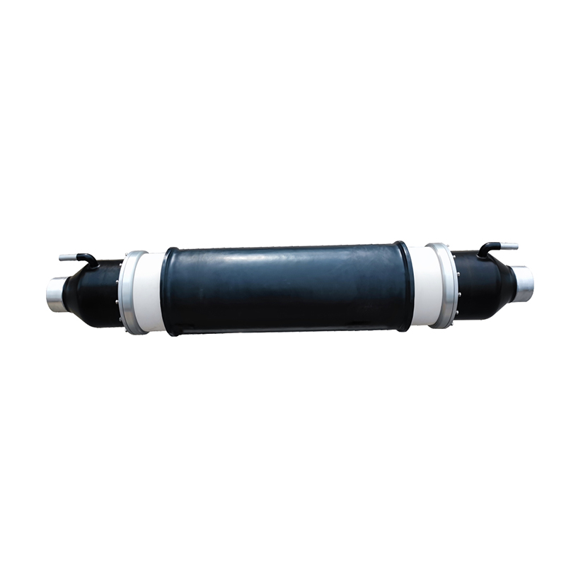
Electrical systems draw more current than they actually put to useful work. Motors, transformers, and other inductive equipment cause voltage and current to fall out of step with each other. That misalignment means extra current flows through wires, switchgear, and transformers without contributing to the output of motors or the heating of elements. Power factor correction capacitor offset that extra current by supplying reactive power locally.
Choosing the right capacitor rating requires attention to the specific conditions at each installation. The existing power factor, the desired power factor, the system voltage, and the load characteristics all affect the final selection. A rating that is too small fails to achieve the intended benefits. A rating that is too large creates overcorrection and can raise voltages beyond acceptable levels. Knowing what goes into the selection process helps those responsible for electrical systems make sensible decisions.
Capacitors in power factor correction applications serve a clear purpose. They deliver reactive power close to the load instead of forcing it to travel from the utility supply through the entire distribution network. That local delivery reduces the total current flowing from the supply for a given amount of useful power.
AC circuits have a particular relationship between voltage and current that changes depending on the type of load. Inductive loads cause current to lag behind voltage. Capacitors cause current to lead. Connecting capacitors in parallel with inductive equipment shifts the current closer to alignment with voltage. Smaller phase angles mean better power factor.
Apparent power is the total power flowing through the circuit. Real power is what actually does the work. The power factor is simply the ratio between these two quantities. A low ratio indicates that a large portion of the current serves no useful purpose. Capacitors reduce the reactive portion of the current, bringing apparent power down toward real power.
Facilities benefit in several ways from improved power factor. Utility companies often charge penalties for low power factor because their equipment must handle the total current, not just the useful portion. Reducing current also lowers losses in cables and transformers. The capacitors themselves require little attention once installed and continue operating for many years when correctly applied.
Gathering accurate information before beginning the calculation prevents errors later. The table below lists the essential data and where to find it.
| Required Data | Where to Obtain It | Role in the Calculation |
|---|---|---|
| Current power factor | Utility statement, power logging meter | Starting point for determining how much correction is needed |
| Target power factor | Utility requirement or facility objective | Defines the end goal for the correction effort |
| Load power or current | Equipment nameplates, load study | Sets the scale of reactive power that must be supplied |
| System voltage | Panel nameplate, measured value | Determines the current rating of the capacitor |
| Supply frequency | Standard utility specification | Affects capacitive reactance |
| Load variation pattern | Operating logs, shift schedules | Accounts for changing conditions throughout the day |
Utility statements often include the power factor averaged over the billing period. For more precise work, power factor meters or recording instruments can be connected at the point where power enters the facility. Taking readings over a full operating cycle captures variations that a single snapshot would miss.
Load conditions matter as much as the total connected equipment rating. Not every motor and transformer runs at the same time. Some loads operate only during certain shifts. Others cycle on and off. A load study that reflects actual operating patterns gives a realistic basis for sizing, rather than assuming all equipment runs simultaneously.
Voltage at the capacitor connection point may differ from the nominal system voltage. Transformer taps, cable losses, and loading conditions all affect the actual voltage. Using measured voltage rather than nameplate values improves the accuracy of the final capacitor selection.
Load conditions rarely remain constant. A rating that performs well at full load may cause problems when loads are lighter. Overcorrection at light load pushes the power factor into the leading range, which can raise voltages and cause equipment issues.
Full load draws the highest current and typically shows the lowest power factor. Capacitors sized for this condition reduce current draw to the target level. When the same motors run at partial load, their power factor changes. The capacitors continue to provide the same reactive power. If that amount exceeds what the reduced load demands, the power factor becomes leading.
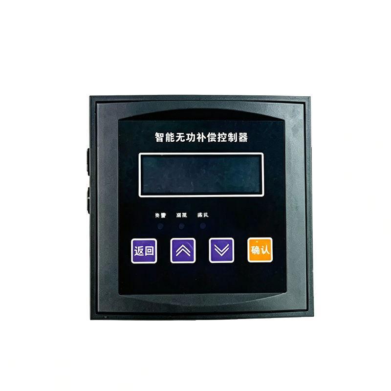
Partial load operation matters for facilities that run at reduced capacity for significant portions of the day. Sizing capacitors for peak load may not be the answer in these cases. Some installations use multiple capacitor steps that can be switched on and off as demand changes. Automatic controllers monitor the power factor and connect only the amount of capacitance needed at any given moment.
Motor starting brings another set of considerations. Starting current can be several times the running current, and the power factor during starting differs from steady-state operation. Capacitors connected while a motor starts can affect starting torque. Some designs disconnect capacitors during starting and reconnect them once the motor reaches running speed.
Tracking down the right information often takes longer than doing the arithmetic. The data needed for capacitor sizing sits in various places around a facility, and knowing where to look makes the process smoother.
Utility statements offer a starting point. Most commercial bills show the power factor averaged over the entire billing cycle. Some include separate line items for reactive power charges. While averaged figures do not reveal peak conditions or daily swings, they provide a general sense of where the facility stands.
Power quality meters give a more complete picture. Portable logging instruments connect at the service entrance or at individual feeders. They record power factor, voltage, current, and harmonics at set intervals over days or weeks. Reviewing the logged data shows when power factor drops, which loads cause the biggest dips, and how long the system stays in a low power factor condition.
Motor nameplates carry useful numbers. Rated power, voltage, current, and power factor at full load all appear on the nameplate. For facilities with a few large motors, nameplate data combined with operating hours gives a workable estimate. For shops with many small motors, sampling a few representative units may be more practical.
Distribution panel meters provide another data source. Many panels have digital displays showing power factor, current, and voltage for each feeder. Taking readings at different times—morning, midday, evening—builds a picture of how the system behaves across the operating day.
Key data sources include:
Voltage and capacitor rating have a direct relationship that needs watching. A capacitor rated for one voltage will draw a different current when connected to another voltage.
Current through a capacitor rises with applied voltage. Connecting a lower-voltage rated unit to a higher-voltage system pushes more current through than the capacitor was designed for. The opposite case—using a higher-rated capacitor on lower voltage—reduces the reactive power output below expectations.
The calculation should use the actual voltage at the connection point. Relying on nominal system voltage can introduce errors if real conditions differ. Measuring voltage during normal operation gives the value to plug into the calculation.
Voltage also varies throughout the day. Lightly loaded transformers often run at higher voltages during off-peak hours. That rise increases the reactive power output of connected capacitors. In some cases, the extra output at higher voltage pushes the system toward overcorrection when loads are light.
Important voltage considerations:
Operating conditions shape how well a capacitor performs and how long it lasts. Temperature heads the list of environmental factors that affect selection.
Capacitors produce heat during normal operation. The surrounding air temperature determines how efficiently that heat escapes. Higher ambient temperatures reduce the capacitor's ability to carry current without exceeding internal temperature limits.
Altitude changes cooling effectiveness. Air density drops at higher elevations, and less air means less cooling. A capacitor that works perfectly at sea level may need derating when installed in mountainous regions.
Enclosure type also matters. Capacitors mounted inside panels or cabinets have less airflow than those in open racks. Enclosed installations may require larger units or forced ventilation to maintain acceptable temperatures.
| Environmental Factor | Effect on Capacitor | Practical Implication |
|---|---|---|
| High ambient temperature | Reduces heat dissipation | Larger unit or derating needed |
| Enclosed mounting | Restricts air movement | Allow extra space or add ventilation |
| High altitude | Lowers cooling efficiency | Derate above certain elevations |
| Moisture or humidity | Affects insulation and terminals | Sealed construction recommended |
| Dusty conditions | Accumulates on surfaces | Periodic cleaning or enclosed design |
Many capacitor suppliers provide derating guidelines for installations above standard temperatures. Operating a capacitor at full rating in a hot environment shortens its service life. Selecting a larger unit that runs at a lower percentage of its rating allows for adequate cooling margins.
Harmonic currents appear in many modern electrical systems. Variable frequency drives, rectifiers, and switching power supplies all produce harmonics. These currents change how capacitors behave in the system.
Capacitors offer low impedance to harmonic currents. That low impedance tends to attract harmonics into the capacitor bank, adding to the fundamental current flowing through the unit. The extra current from harmonics can push the capacitor beyond its current rating.
Resonance presents a particular hazard. When the inductive reactance of the transformer and supply matches the capacitive reactance of the bank at a harmonic frequency, high circulating currents develop. That resonant condition can cause overvoltage, overheating, and rapid capacitor failure.
Some installations need capacitors built specifically for harmonic duty. These units use thicker film, heavier connections, and higher temperature ratings to handle the extra stress. In systems with known harmonic content, standard capacitors may not survive.
Key harmonic considerations:
Checking harmonic conditions before buying capacitors prevents problems later. A power quality survey that measures harmonic levels at the proposed connection point provides the information needed to choose between standard and harmonic-rated units.
How the capacitor connects to the system affects performance, reliability, and safety. Several arrangement options exist, each with its own advantages and trade-offs.
A single large capacitor serving the entire facility offers the simplest installation. Fewer components means lower equipment costs and less space required. The drawback is fixed reactive power output regardless of load conditions. When load varies, one large unit cannot adapt.
Multiple smaller units connected in steps provide flexibility. Each step switches on or off as reactive demand changes. Automatic controllers monitor power factor and connect only the capacitance needed at any moment. This arrangement handles variable loads better than a single fixed unit.
Individual correction places small capacitors at each motor or load. Reactive power gets supplied exactly where needed, reducing current in branch circuits. Total capacitance spreads across many small units rather than concentrating in one location.
Installation points to consider:
Protection and switching deserve attention. Fuses guard against short circuits. Discharge resistors allow the capacitor to safely lose its charge after disconnection. Switching devices must be rated for capacitor duty, which involves higher inrush currents than typical switching applications.
Sizing a power factor correction capacitor requires pulling together information from several sources and thinking beyond the basic arithmetic. The existing power factor, target power factor, load patterns, voltage conditions, and environmental factors all shape the final choice. Harmonics add extra complexity in systems with electronic loads.
The calculation forms only part of the work. Data collection, observation of operating patterns, and attention to installation conditions all contribute to a successful outcome. A capacitor that matches the actual site conditions delivers the expected benefits without introducing new problems.
Getting the details right pays off in system performance and equipment life. The correct capacitor rating reduces current draw, lowers losses, and avoids utility penalties while operating reliably for many years. Understanding what goes into the selection process helps ensure the installed equipment serves the facility's needs effectively.
The variety of models, to meet the development needs of various regions in the world.
Copyright © Shanghai Yongjin Electric Technology Co.,Ltd.

China Power Quality Solutions Supplier