English
 中文简体
中文简体 русский
 Español
 عربى
عربى
Industry News
Home / News / Industry News / How a Capacitor Bank Differs From a Single Power Factor Correction Capacitor
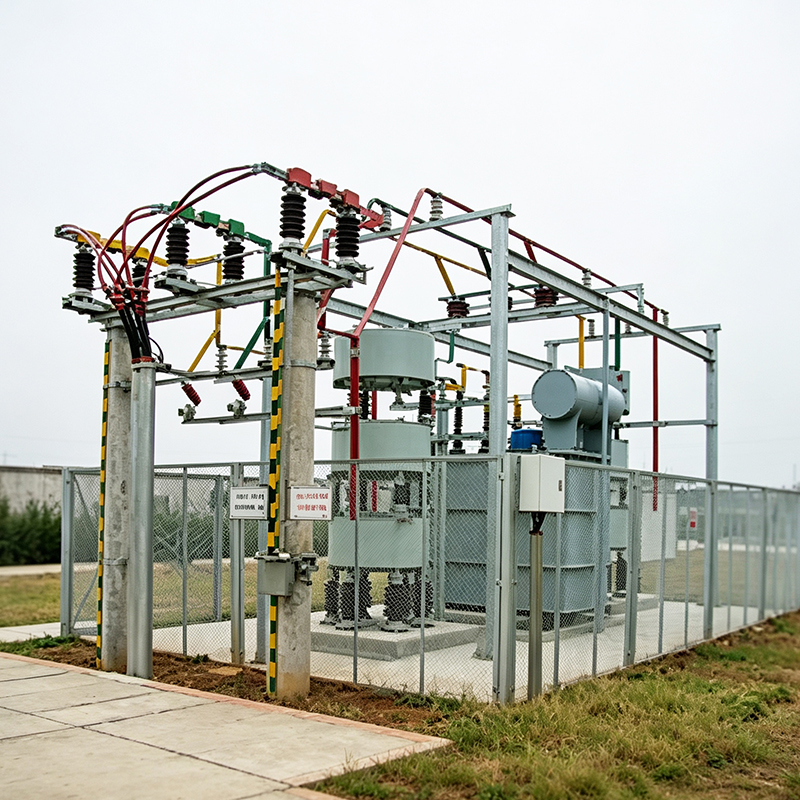
Electrical panels in industrial and commercial spaces often hold more than switching parts and protection devices. Behind the door, a power system may be dealing with motors, pumps, fans, processing lines, and other inductive loads that keep drawing reactive power while the facility keeps running. In ordinary operation, that behavior stays in the background, yet the effect reaches every cable, busbar, and transformer connected to the system.
A single power factor correction capacitor and a Capacitor bank both deal with that same reactive condition, though the way each one works inside a panel is not the same. One brings a fixed correction point into the circuit, while the other creates a staged arrangement that can follow changing demand across different operating periods. In facilities where load levels stay steady, a single unit may do enough of the job. In systems where machines start and stop through the day, or where production lines shift with the work schedule, a bank arrangement usually fits the operating pattern better.
The difference is not only about size or quantity. It is about response, coordination, and how closely compensation matches the real electrical condition inside the panel.
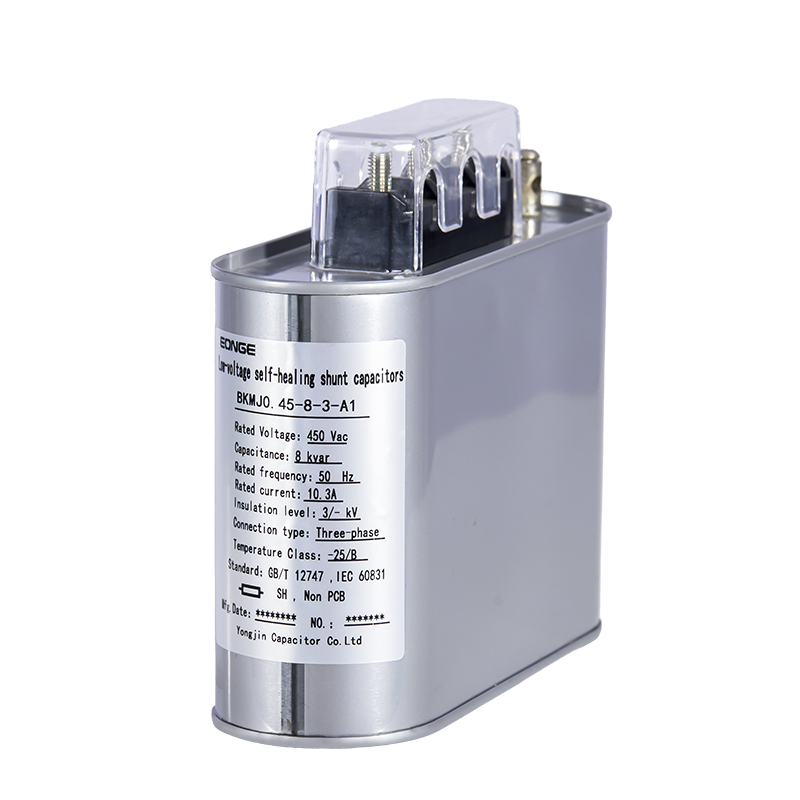
A single power factor correction capacitor is built to provide a steady amount of reactive support at one point in the system. It stores energy in an electric field and releases it in a way that offsets part of the reactive demand created by inductive equipment. The idea is simple, and that simplicity is the main reason the device remains in common use.
In a panel or near a load, the capacitor works as a local helper for equipment that needs magnetic fields to operate. A motor, for example, pulls reactive power while it runs, and the capacitor can supply part of that requirement from nearby instead of sending all of it through the wider distribution path. The system still performs the same work, yet the current traveling through upstream components can be reduced.
That fixed response suits many stable operating cases. When a load remains close to the same level through long periods, a single capacitor can stay in place and continue providing the same correction without frequent change. The arrangement is direct, compact, and easy to understand. There are fewer internal stages, fewer control layers, and fewer moving parts involved in the correction process.
Common traits of a single capacitor include:
The fixed nature of the device makes it useful where demand does not move far from one operating point. Once the size is selected and installed, the unit simply performs its role in the background.
A Capacitor bank takes the same correction idea and builds it into a grouped arrangement. Instead of one unit doing one fixed task, several capacitor sections work together in a coordinated panel layout. The system can turn different stages on or off according to operating conditions, which gives the panel a more flexible way to handle changing load patterns.
That flexibility matters in facilities where electrical demand is not steady. Some machines run for long stretches, some equipment starts only at certain points in the process, and other loads may drop out or come back according to production needs. A bank arrangement can follow those shifts more closely than a single fixed capacitor.
Inside the panel, the bank behaves like a structured compensation system rather than a standalone device. It is still concerned with reactive power, yet it does the work through staged response instead of a single output level. That staged behavior helps the electrical system stay closer to the actual load pattern during different parts of the day.
The bank structure gives the panel room to respond when electrical behavior changes. Instead of forcing one fixed level of correction on every condition, the system can adapt as the load changes.
The difference between the two approaches becomes easier to see when structure and behavior are placed side by side. A single capacitor gives one correction point.
| Aspect | Single Capacitor | Capacitor bank |
|---|---|---|
| Structure | One unit | Several coordinated units |
| Compensation | Fixed | Adjustable in stages |
| Response to load change | Limited | Flexible |
| Panel integration | Simple | More organized system layout |
| Control behavior | Minimal | Coordinated switching |
| Suitable operating pattern | Stable load | Variable load |
That contrast shapes how each solution is used in practice. A single capacitor can work well where the electrical demand stays close to one level. A bank becomes more useful where demand rises and falls through normal operation, because the system can bring stages in or out as needed.
The structural difference also changes how the panel feels from a maintenance and operating perspective. A single device is easier to picture and check. A bank introduces more coordination, though it also offers a better fit for changing environments.
Electrical load rarely stays in one state for very long in active industrial environments. Motors begin and stop, pumps cycle, ventilation systems shift with air demand, and production lines move through different phases. Each shift changes the reactive behavior of the overall network.
A Capacitor bank handles that condition through staged correction. When the load rises, more capacitor sections may be connected. When the load eases, some of those sections can be taken out. The goal is not to overcorrect or undercorrect, but to keep the compensation level close to the demand pattern that exists at that moment.
That adaptive behavior is the key reason banks are often used in facilities with changing loads. The system is not locked into one correction value. It can move with the electrical conditions rather than standing apart from them.
Typical response patterns include:
This kind of behavior gives the panel a more active role in system balance. The bank is not just installed and left alone. It continues adjusting as the facility shifts from one operating condition to another.
A single capacitor does one thing well. It provides a set amount of reactive support. That is also where the trouble starts. Once installed, that amount does not change. The load it serves might change, but the capacitor stays the same.
Walk through any facility with mixed operations and the pattern becomes clear. Morning shift runs everything at full capacity. Afternoon shift scales back. Evening shift might run only essential equipment. A single capacitor sized for the morning rush will overcorrect in the evening. Sized for the evening, it undercorrects in the morning.
The same problem shows up with equipment that cycles frequently. Motors start up, draw heavy current, then settle into running mode. A single capacitor cannot tell the difference between starting and running conditions. It either stays connected throughout or drops out entirely. Neither choice fits both situations well.
Overcorrection brings its own headaches. Too much capacitance can cause voltage rise on the system. Equipment connected to that bus may see higher than intended voltage levels. Undercorrection leaves reactive current flowing through cables and transformers, taking up capacity that could carry working power.
Some facility operators try to work around these limits by choosing a middle value. They pick a capacitor that lands somewhere between the highest and lowest load levels. This compromise means the system stays overcorrected part of the time and undercorrected the rest. Neither state is ideal, but neither is completely wrong either.
The real limitation shows up in facilities where loads change unpredictably. Production schedules shift. Equipment gets added or removed. Operating patterns evolve over months and years. A single capacitor installed five years ago may no longer match the load it serves today. The device itself has not changed, but everything around it has.
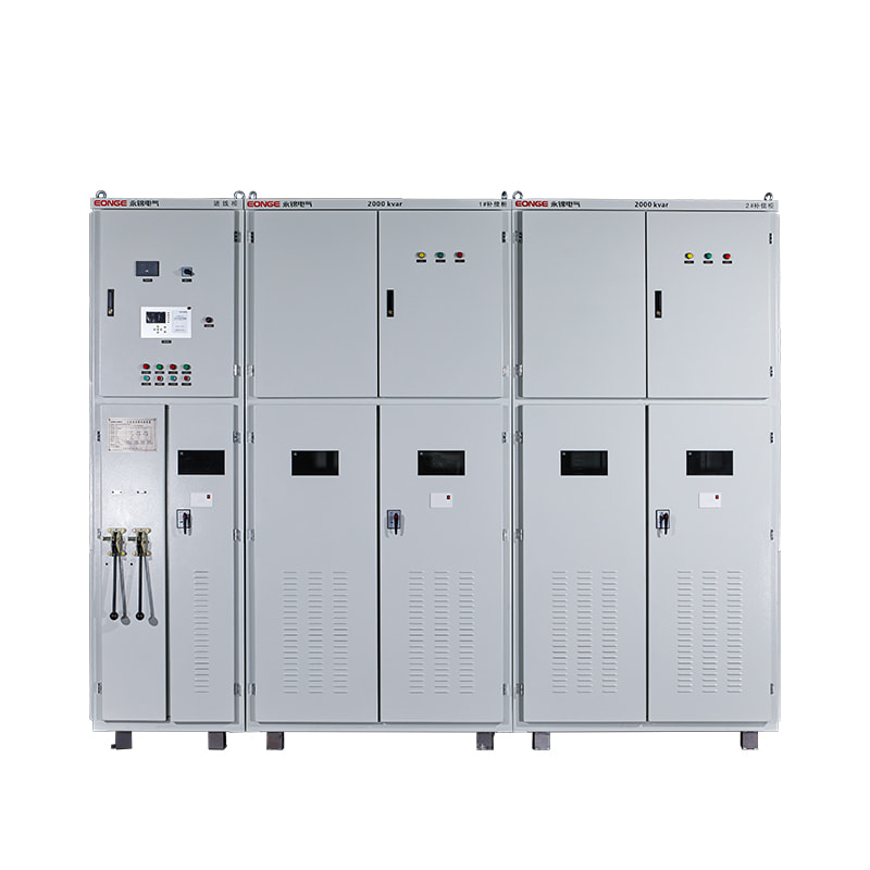
Open the door of a capacitor panel and the first thing that catches the eye is organization. Components sit in clear arrangement, each with its own place and purpose.
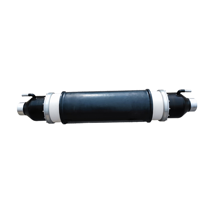
The capacitor units themselves take up a good portion of the space. These are the parts that actually do the correction work. They store energy and release it in a way that offsets reactive demand. Each unit handles part of the total compensation, and together they cover the range the facility needs.
Nearby sit the switching devices. These connect or disconnect individual stages based on what the control system tells them. Contactors are the usual choice, though other switching technologies appear as well. They have to handle the surge that comes when a capacitor connects to the network—that moment when current rushes in to charge the unit.
Protection devices are scattered through the panel too. Fuses or circuit breakers guard against overcurrent. Some panels include harmonic filters or other protective elements. These devices keep the system from damaging itself when conditions get rough.
The control module sits somewhere accessible. This is the brain of the operation. It watches voltage, current, and power factor. It decides when to switch stages on and off. The settings in this module determine how the bank behaves—how fast it responds, what target it aims for, how much it lets things drift before making changes.
All of these components live inside a common enclosure. The panel structure organizes the layout, provides mounting points, and allows for ventilation. Heat builds up inside any electrical enclosure, and capacitors especially dislike high temperatures. Good panel design keeps that heat under control.
The Capacitor Bank Manufacturer does more than assemble parts into a box. Design decisions made before assembly affect how the bank performs once installed.
Stage sizing is one of those decisions. The total compensation needs to cover the facility's range, but the step size matters too. Large stages mean fewer steps but coarser control. Small stages give finer adjustment but more components and more complexity. The manufacturer helps find a balance that suits the application.
Panel layout affects maintenance and service life. Components that generate heat should not sit too close together. Items that need regular checking should stay accessible. Cable entries should make sense for the installation site. These details are easy to overlook but make a real difference once the panel is mounted and wired.
Control settings need adjustment for each site. A bank responding to voltage behaves differently from one responding to power factor. The manufacturer typically provides guidance on settings, though the final tuning often happens during commissioning. Some installations need fast response to catch rapid load changes. Others prefer slower adjustments to avoid frequent switching.
Manufacturers also deal with environmental factors. A panel going into a clean electrical room has different requirements than one sitting in a dusty factory or an outdoor enclosure. Enclosure ratings, ventilation design, and component selection all reflect where the bank will live and work.
A bank system changes more than the point where it connects. The effect travels upstream through the distribution network.
Less reactive current means less heating in cables. Cables that carry less current run cooler. Cooler cables last longer and need less attention. The same holds for transformers—when reactive current drops, the transformer can carry more active power without exceeding its rating.
Voltage stability sees improvement too. Reactive power and voltage are closely linked in distribution systems. When reactive demand exceeds supply, voltage drops. The bank supplies reactive power locally, which helps maintain voltage levels. Equipment across the facility benefits from this, not just the loads near the bank.
The staged nature of the bank makes it useful across multiple load points. Instead of installing individual capacitors at each motor, a single bank can serve a group of loads. The bank follows the combined demand of that group, adjusting as individual machines start and stop.
These improvements happen without the bank achieving any particular target. They follow simply from reducing the amount of reactive current that flows through the distribution system. The bank does its work in the background, and the system runs more smoothly as a result.
Keeping a capacitor in good condition does not require a lot of specialized knowledge. Regular attention and basic observation go a long way.
Visual checks catch many problems early. Looking at the panel enclosure, checking for signs of overheating, noticing any discoloration on components—these simple actions give useful information. Swollen capacitor cases, burnt contact surfaces, or loose connections all show up during a careful walk-through.
The control module keeps records of switching activity. Looking at these records reveals patterns. One stage switching more often than others might indicate uneven stage sizing. Stages that never activate may be oversized for the actual load. These patterns provide clues about how well the bank matches the facility's needs.
Temperature matters. Capacitors have rated operating ranges, and heat shortens their service life. Checking ventilation openings, keeping filters clean, making sure cooling fans run properly—these tasks help keep internal temperatures within reason.
Dust inside the panel can cause problems. It reduces clearances, traps heat, and can interfere with moving parts. A regular cleaning schedule keeps the interior clear without requiring special tools or training.
Catching issues early makes maintenance easier. A capacitor that starts to bulge gives warning well before failure. A stage that takes longer than usual to engage points to contact wear or control problems. Dealing with these signs when they first appear avoids emergency repairs later.
The electrical world keeps changing. More facilities run automated processes. Variable-speed drives appear on more equipment. Load patterns grow more complex. These changes create new demands for correction equipment.
Capacitor fit this evolving picture because they can keep up with changing conditions. The staged approach allows them to follow load variations without constant operator attention. Control systems handle the adjustments automatically, switching stages on and off as needed.
Commercial buildings have joined industrial facilities in using bank systems. Office towers, hospitals, and retail centers all have inductive loads—HVAC equipment, elevators, cooling systems. These loads behave similarly to industrial equipment, though on a different scale. The same principles apply.
Integration with other systems has become more common. Some facilities coordinate bank operation with production schedules or energy management programs. This coordination might mean avoiding switching during certain periods or aligning compensation with planned load changes. The bank becomes part of a broader strategy rather than operating in isolation.
The need for reactive power support is not going anywhere. Motors and transformers remain essential to facility operation. Banks offer a response that can adapt as facilities grow and change. That adaptability keeps them relevant even as the electrical environment continues to evolve.
The variety of models, to meet the development needs of various regions in the world.
Copyright © Shanghai Yongjin Electric Technology Co.,Ltd.

China Power Quality Solutions Supplier