


 English
 中文简体
中文简体 русский
 Español
 عربى
عربى
Industry News
How a Power Factor Correction Capacitor Reduces Reactive Power Demand
Electrical loads do not all use supplied power in the same way. Motors, transformers and other inductive equipment need active power for their working tasks, while part of the electrical energy moves back and forth within the system as reactive power.
Reactive power does not directly perform useful mechanical work. It is associated with the magnetic fields required by many AC loads. Even though it does not represent the same kind of energy use as active power, it still affects the electrical current carried through a supply system.
A simple way to view the relationship is to separate three forms of electrical power:
- Active power supports useful work such as driving a motor.
- Reactive power supports the magnetic or electric fields associated with AC equipment.
- Apparent power reflects the combined electrical demand seen by the supply.
Power factor describes the relationship between active power and apparent power. A lower power factor means that more current is needed to deliver a given amount of useful active power.
Inductive loads commonly create a lagging power factor because their magnetic fields require reactive support. When many such loads operate together, reactive demand can become an important part of the electrical system.
A power factor correction capacitor addresses part of that condition by supplying capacitive reactive power close to the load or within the distribution system. Rather than asking the upstream supply to provide all of the reactive support, part of that requirement is handled locally.
How a Power Factor Correction Capacitor Responds to Reactive Power
A capacitor behaves differently from an inductive load in an AC circuit. An inductive load draws reactive power, while a capacitor supplies reactive power. Placing suitable capacitive support into a system can therefore offset part of the reactive demand created by inductive equipment.
Imagine a motor connected to a distribution line. During operation, the motor needs active power for mechanical work and also requires reactive power associated with its magnetic operation. Without compensation, both components travel through the upstream electrical path.
Adding a power factor correction capacitor changes that relationship. Capacitive reactive current becomes available near the load, reducing the amount of reactive current that needs to travel from the source.
The basic process can be viewed as:
- Inductive load → Reactive demand
- Capacitor → Capacitive reactive support
- Combined system → Lower reactive demand from the supply
Such compensation does not remove the motor's need for active power. Mechanical work still requires active energy. Instead, correction changes where reactive support comes from and reduces unnecessary reactive flow through parts of the distribution system.
Placement can therefore matter. A capacitor positioned close to an inductive load can provide reactive support locally, while a central installation may serve several loads within a broader distribution arrangement.
How Capacitive and Inductive Loads Work Together
Inductive and capacitive behavior can be viewed as opposing parts of AC power flow. Motors and transformers commonly have an inductive character, while capacitors introduce a capacitive response.
When an inductive load operates alone, reactive current moves through the supply path along with active current. Adding suitable capacitance creates another reactive current component that offsets part of that demand.
The relationship is easier to picture through a simple sequence:
- Inductive equipment creates reactive demand
- Capacitive equipment provides reactive support
- Part of the reactive flow is balanced locally
- Supply-side current can decrease
Such balancing needs to match actual operating conditions. Too little correction leaves part of the reactive demand unchanged. Too much correction can shift the electrical condition toward excessive capacitive behavior.
For that reason, power factor correction is not simply a matter of adding as much capacitance as possible. Load characteristics, operating patterns and the rest of the electrical system need to be considered together.
Another point deserves attention: reactive compensation does not mean the connected machine suddenly requires less mechanical energy. A motor still performs its intended work. Correction mainly changes the relationship between active and reactive components seen by the supply.
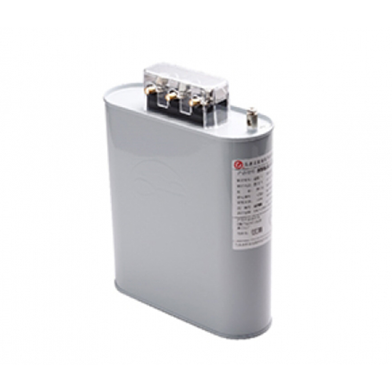
How Power Factor Correction Changes Current Flow
Current is one of the clearest areas where power factor correction can have an electrical effect. For a given amount of active power, a lower power factor requires greater apparent power and therefore greater supply current.
When a capacitor supplies part of the reactive requirement, the upstream system carries less reactive current. As a result, total current through sections between the source and compensated load can decrease.
The effect is particularly relevant in facilities containing several inductive loads. Motors may operate at different times, creating a changing reactive demand. Correction equipment can be arranged to respond to those changes rather than treating the entire system as a fixed load.
| Electrical Condition | Supply Side Response |
|---|---|
| High inductive demand | More reactive current travels from the source |
| Partial correction | Part of reactive demand is supplied locally |
| Suitable correction | Lower reactive flow through upstream conductors |
| Excessive correction | System may become overly capacitive |
Lower current can reduce electrical losses in conductors and reduce the current burden on distribution equipment. It can also make better use of available electrical capacity, since less of that capacity is occupied by reactive current.
Actual results depend on the complete system arrangement. A capacitor installed near one load mainly affects the electrical path between that load and the supply point. A centralized arrangement can influence a wider section of the distribution network.
Where Power Factor Correction Capacitors Are Used
Power factor correction is commonly associated with equipment that has an inductive electrical character, particularly motor-driven systems. Industrial facilities, commercial buildings and other electrical installations can contain several such loads operating at different times.
A steady load can allow a relatively simple correction arrangement because reactive demand changes little during normal operation. A changing load requires greater attention to how much capacitance remains connected at each stage.
Location also affects the purpose of correction.
A capacitor installed near a particular motor can provide local reactive support. A central capacitor arrangement can serve a group of loads through a shared distribution point.
Selection therefore needs to begin with the actual electrical layout rather than the capacitor alone. Engineers generally consider where reactive demand appears, how loads operate and which section of the system needs correction.
For facilities with several operating areas, the relationship between local and central compensation can become an important part of electrical planning.
How Load Changes Affect Capacitor Selection and Control
Electrical loads rarely remain identical throughout an entire working period. Motors may start, stop or change their operating condition, causing reactive demand to move along with them.
A fixed capacitor can suit a relatively stable load, particularly where its operation is closely connected with a specific machine. Variable loads require a different approach because leaving the same amount of capacitance connected during every operating condition may not match the actual reactive requirement.
A stepped arrangement can respond by connecting or disconnecting sections of capacitance as demand changes. Control equipment can monitor the electrical condition and adjust the available correction accordingly.
Such control creates a more flexible relationship:
Load changes → Reactive demand changes → Correction level changes
Rather than treating compensation as a permanent fixed value, the system can respond to the actual operating state.
How Harmonics Influence Capacitor Applications
A power factor correction capacitor does not operate in isolation from the rest of an electrical system. Loads such as drives, switching equipment and other electronic devices can create current waveforms that differ from a simple AC waveform. Harmonic currents can then become part of the operating environment around a capacitor.
Reactive power compensation and harmonic control are related, yet they are not the same task. A capacitor can help offset reactive demand from an inductive load, while harmonic problems require attention to waveform distortion and system interaction.
Poorly matched correction equipment may experience unwanted electrical stress when harmonic currents are present. Resonance can also become a concern when capacitance interacts with inductive elements in the distribution network.
For practical planning, several questions deserve attention:
- What types of loads are connected?
- Does the load create waveform distortion?
- Does reactive demand remain stable?
- Where will correction equipment be installed?
- Could switching capacitance change the electrical condition?
A facility with simple motor loads may have different correction requirements from a workspace containing many electronic power converters. Treating both situations in exactly the same way can create unnecessary operating problems.
Harmonic conditions should therefore be checked before selecting capacitor capacity or deciding how correction stages will operate. Reactive power reduction remains useful, yet the surrounding electrical environment determines how that reduction should be achieved.
What Changes After Reactive Power Demand Is Reduced
When suitable capacitance is connected near an inductive load, part of the reactive requirement can be supplied locally. Less reactive current then needs to travel through the upstream section of the electrical network.
A useful comparison looks like this:
| Before Correction | After Suitable Correction |
|---|---|
| Supply provides more reactive support | Part of reactive support comes from capacitors |
| Higher apparent power demand | Lower apparent power demand |
| Greater current in upstream conductors | Lower upstream current |
| More distribution capacity used by reactive flow | More capacity available for active loads |
Reduction in reactive current does not mean that a motor suddenly consumes less active energy for the same mechanical task. Useful work still requires active power. What changes is the amount of additional current associated with reactive demand.
Lower current can also reduce losses in conductors because electrical losses are related to current. Distribution equipment may experience a lighter current burden as well, especially along sections located upstream from the correction point.
Location matters here. A capacitor placed directly beside a load can reduce reactive current in the cable feeding that load. A centrally located arrangement may influence several branches at once, while sections between individual loads and a central correction point can still carry their local reactive current.
For that reason, the physical position of correction equipment should be considered alongside its electrical capacity.
Where Correction Capacitors Fit Into Electrical Systems
A correction capacitor can be installed close to an individual load, within a distribution panel or as part of a broader capacitor arrangement. Each approach responds to a different system structure.
Local correction can make sense where one inductive machine has a relatively stable operating pattern. Reactive support is then available near the point where demand occurs.
Central correction may suit an installation containing several loads that share a distribution system. A central arrangement can respond to combined demand rather than requiring individual correction at every machine.
Load behavior remains important. A facility where equipment starts and stops throughout the working period may need a correction arrangement that changes with demand.
A practical review can consider:
- Whether loads operate continuously or intermittently
- Whether several machines share one distribution section
- Whether reactive demand changes during normal operation
- Whether correction needs to follow load changes
- Whether harmonic conditions exist within the system
Installation location also affects maintenance. Equipment placed in an accessible electrical area may be easier to inspect, while local correction can require attention at several machine locations.
How Load Changes Affect Capacitor Control
A fixed amount of capacitance can work with a relatively stable load. Problems can appear when the electrical demand changes considerably during normal operation.
Suppose several motors operate during one period and only a small portion of the equipment remains active later. A correction level suitable for the heavier condition may become excessive during the lighter condition.
Automatic switching can address such variation by connecting or disconnecting capacitor sections according to the electrical state. Rather than keeping every capacitor section active continuously, control equipment can adjust the available reactive support.
A staged arrangement may follow a pattern such as:
- Low load → Small correction requirement
- Higher load → Additional correction connected
- Load decreases → Unneeded correction removed
Such control helps maintain a closer relationship between actual reactive demand and available capacitive support.
Careful control also reduces the chance of excessive capacitive correction. An electrical system does not necessarily benefit from keeping every correction stage connected at all times. Matching the correction level with operating conditions remains an important part of system design.
What Should Be Considered Before Using a Correction Capacitor
Selecting a power factor correction capacitor should begin with the electrical system rather than with a capacitor rating alone. Load behavior, installation position, operating voltage and harmonic conditions all influence the final arrangement.
A useful evaluation can begin with the following areas:
- Load Type
Identify which machines or equipment create inductive reactive demand. Motors and transformers often require particular attention. - Operating Pattern
Check whether loads remain steady or change throughout normal operation. Variable demand may require switched correction. - Existing Power Factor
Review the existing electrical condition before deciding how much correction is needed. A correction level should have a clear relationship with actual reactive demand. - Installation Position
Consider whether local or central compensation fits the distribution structure. Current flow through cables and distribution equipment can differ depending on placement. - Harmonic Environment
Check whether electronic loads create waveform distortion. Capacitor behavior can be affected by the surrounding electrical network. - Protection and Switching
Correction equipment needs appropriate switching and protective arrangements. Frequent connection and disconnection can place additional demands on associated components. - Maintenance
Inspection access, connection condition and operating status should remain practical throughout normal service.
How Reactive Power Compensation Fits Into Electrical Management
Reactive power correction works as part of a wider electrical management process. A power factor correction capacitor changes the relationship between inductive demand and capacitive support, reducing the reactive component carried through selected parts of the system.
Actual performance depends on how closely the correction arrangement matches the working environment. A stable motor load, a variable production area and an installation with many electronic loads can require different approaches.
A sensible process can follow a clear sequence:
Identify the load → Review reactive demand → Check operating changes → Examine harmonics → Select correction method → Choose installation position → Monitor system behavior
Such a process keeps capacitor selection connected with real operating conditions rather than treating power factor correction as a simple equipment addition.
Reactive power itself is not an unnecessary part of AC operation. Many electrical machines require it for normal operation. The practical goal is to avoid making the upstream distribution system carry reactive demand that can be supplied closer to the load.
Once load behavior, capacitor response, current flow and system conditions are considered together, power factor correction becomes easier to manage as part of everyday electrical system planning.
Recommended Products
The variety of models, to meet the development needs of various regions in the world.
Copyright © Shanghai Yongjin Electric Technology Co.,Ltd.

China Power Quality Solutions Supplier