


 English
 中文简体
中文简体 русский
 Español
 عربى
عربى
Industry News
How to Connect a Capacitor Bank to a Three Phase Power Supply
Industrial electrical systems often contain motors, transformers, and other loads that interact with electrical power differently from simple resistive equipment. Part of the supplied energy moves between the source and magnetic components rather than being converted directly into mechanical or thermal work. Such behavior affects the relationship between current and useful power within a three phase system.
A Capacitor bank can be connected in parallel with a load or distribution section to provide reactive power near the point where it is required. Local compensation can change the current relationship within upstream parts of the electrical system and may reduce unnecessary loading under suitable operating conditions.
Power factor is closely related to the process. A system with a lower power factor may require more current to deliver a given amount of useful power. Improving the relationship between useful power and supplied current can therefore help make better use of existing electrical capacity.
Application planning should begin with the load rather than with the compensation equipment. A facility with frequently changing motor loads may have different requirements from a site where electrical demand remains relatively stable. Fixed compensation and automatic switching are consequently suited to different operating patterns.
A basic assessment normally considers:
- Type of electrical loads
- Changes in load during operation
- Existing power factor
- Available installation space
- Electrical protection requirements
- Compatibility between compensation equipment and the supply
Compensation equipment should not be added without considering the complete electrical system. Incorrect selection or connection can create operating problems, making a preliminary assessment an important part of installation planning.
What Should Be Checked Before Connecting A Capacitor Bank
Preparation begins with identifying the electrical characteristics of the three phase supply. Rated voltage, frequency, phase arrangement, load behavior, protection arrangements, and existing electrical equipment all influence whether a proposed unit is suitable.
Load characteristics deserve particular attention. Motors that start and stop frequently create a different operating pattern from equipment that runs under relatively stable conditions. A compensation system designed without considering such changes may switch too often or remain connected when additional support is not needed.
Installation location also matters. Adequate space, ventilation, protection, and inspection access should be available around the equipment. Heat, moisture, dust, and corrosive surroundings can influence operating conditions and may affect the service environment.
Electrical compatibility should be confirmed before connection work begins. Ratings need to correspond with the supply and intended application, while protective devices should be selected as part of the complete installation rather than viewed as separate accessories.
| Area | What Needs Attention |
|---|---|
| Supply | Voltage, frequency, and phase arrangement |
| Load | Type, operating pattern, and variation |
| Compensation unit | Rating and intended role |
| Protection | Isolation and protective arrangements |
| Location | Ventilation, access, moisture, and heat |
| Control | Fixed or automatic switching requirements |
Safety is separate from technical suitability. Electrical installation involving energized or potentially energized equipment should be handled by qualified personnel using procedures appropriate for the local electrical system.
How Is A Capacitor Bank Connected To A Three Phase Supply
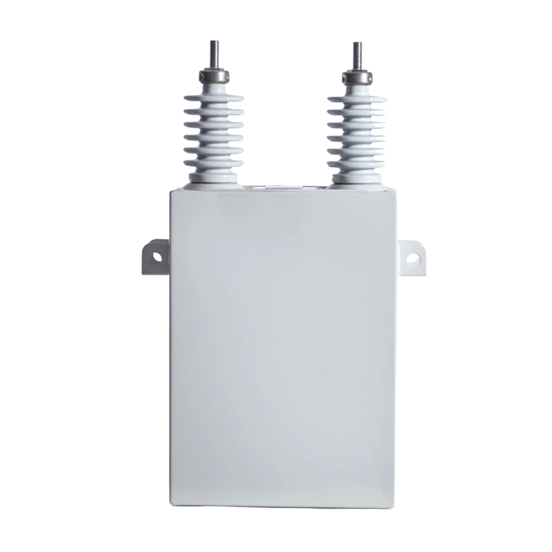
A unit used for power factor correction is generally connected in parallel with the relevant electrical load or distribution section rather than placed directly in series with the load. Parallel connection allows reactive power to be supplied near the load while the main equipment continues receiving power from the three phase source.
A typical arrangement contains a three phase source, a distribution point, protective equipment, switching equipment, and the compensation unit. Exact connections depend on equipment construction and the electrical design of the installation.
Conceptually, the relationship can be viewed as:
Three Phase Supply → Distribution Point → Load
with the compensation equipment connected across the appropriate three phase section.
Such an arrangement allows reactive support to occur close to the load. When a motor requires reactive power, a properly selected unit can provide part of that requirement locally, reducing the amount of reactive current moving through upstream conductors.
Actual terminal connections should always follow the equipment documentation and electrical design prepared for the installation. A general connection diagram cannot replace manufacturer instructions because terminal arrangements, switching methods, protective requirements, and internal construction may vary between products.
Phase identification deserves careful attention as well. A three phase installation depends on correct electrical relationships between phases, so an incorrect connection can result in abnormal operation or create a safety hazard.
Before energization, qualified personnel should verify:
- Correct phase identification
- Correct terminal connections
- Appropriate protective devices
- Secure conductor connections
- Suitable isolation arrangements
- Proper grounding and protective measures
Connecting compensation equipment therefore involves more than attaching conductors to a power source. Equipment selection, protection, switching, system conditions, and installation design all form part of the process.
What Components Are Needed Around The Capacitor Bank
A compensation unit normally operates as part of a larger electrical arrangement. Capacitors provide reactive support, while surrounding components control operation and help protect the equipment during abnormal conditions.
Switching equipment becomes important when compensation needs to change with the load. A fixed arrangement may remain connected under suitable conditions, whereas an automatically controlled system can add or remove stages according to electrical demand.
Protection provides another layer of control. Electrical faults, abnormal current conditions, and equipment problems need to be addressed through suitable protective arrangements. Exact methods depend on system design and equipment configuration.
Isolation is equally important during inspection and maintenance. Personnel need a clear means of separating the equipment from the electrical supply before work begins, followed by appropriate verification that the equipment is safe to handle.
Control equipment can monitor relevant electrical conditions and determine when additional compensation is required. In an automatic arrangement, separate stages can be introduced or removed according to changes in demand.
A basic functional structure can be viewed as:
Supply → Protection → Switching → Compensation Stages
with the control section coordinating switching according to system conditions.
Each component has a separate role. Protection should not be treated as a substitute for switching, while switching should not replace isolation. Keeping those functions distinct helps create a clearer installation arrangement.
How Does Automatic Switching Work
Electrical loads rarely remain constant throughout an operating period. Motors may start, stop, or change working conditions, causing reactive power requirements to move up and down.
An automatically controlled system responds by switching individual stages into or out of service. Rather than keeping every stage connected continuously, the controller can select a suitable combination according to current demand.
For example, a facility may have a lower reactive requirement during light operation and a higher requirement when several motors are running. Automatic switching can respond to such changes rather than maintaining one compensation level throughout the entire operating cycle.
A staged arrangement allows gradual adjustment. Smaller changes in demand can be handled with fewer stages, while greater demand may require additional stages.
Careful control remains important because excessive capacitance can create overcompensation. Such a condition may produce an electrical state different from the intended operating condition and can affect system behavior.
Automatic control should therefore reflect the actual characteristics of the installation. Controllers, switching devices, capacitor stages, and protective arrangements need to work together rather than being selected independently.
For a Capacitor Bank Manufacturer, understanding the customer's load pattern is relevant during product configuration. A system intended for a stable load may require a different control arrangement from equipment installed where demand changes frequently.
Current industry practice increasingly considers compensation equipment together with load profiles, switching behavior, protection, and maintenance requirements instead of treating the equipment as an isolated component.
What Safety Checks Are Needed During Installation
Installation work requires careful preparation because stored electrical energy can remain present after the main supply has been disconnected. Switching off the incoming supply is therefore only one part of the preparation process.
A qualified electrical worker should follow the isolation procedure required for the installation, verify the absence of voltage, and allow suitable discharge arrangements to operate before touching relevant components. Personal protective equipment and appropriate tools should match the work being performed.
Physical inspection also matters. Before energizing a newly installed unit, connections should be checked for looseness, damaged insulation, incorrect routing, or contact with nearby metal parts. Conductors should be arranged so vibration, heat, or movement does not place unnecessary stress on terminals.
Grounding and protective connections need separate attention. A reliable protective path can reduce electrical risk during an insulation fault or another abnormal condition.
Environmental conditions should be reviewed as well. Equipment installed in a hot, damp, dusty, or poorly ventilated area may experience conditions different from those considered during selection.
A practical installation check can cover:
- Supply isolation
- Absence of voltage
- Discharge condition
- Terminal connections
- Protective connections
- Cable routing
- Ventilation
- Enclosure condition
- Switching equipment
- Clearance around the installation
Energization should take place only after the complete installation has been inspected. Qualified personnel can then monitor initial operation and look for unusual sounds, smells, heating, switching behavior, or other signs of abnormal operation.
Safety should remain part of installation, commissioning, and maintenance rather than being treated as a final inspection step.
How Can A Capacitor Bank Manufacturer Support Proper Application
A Capacitor Bank Manufacturer is involved in more than producing the capacitor assembly itself. Product configuration needs to relate to the electrical environment where equipment will operate, so information about supply conditions and load behavior can influence selection.
Different facilities have different operating patterns. A site with motors running for long periods may have relatively stable compensation requirements, while another location may experience frequent changes in electrical demand. Such differences can affect switching arrangements and stage configuration.
Technical documentation also has an important role. Clear terminal information, connection instructions, operating conditions, protection recommendations, and maintenance guidance help installers incorporate equipment into the wider electrical system.
Product selection can therefore consider several areas together:
| Application Factor | Why It Matters |
|---|---|
| Supply conditions | Determines electrical compatibility |
| Load behavior | Influences compensation requirements |
| Switching pattern | Affects control arrangement |
| Installation environment | Influences operating conditions |
| Protection design | Helps manage abnormal conditions |
| Maintenance access | Supports inspection and servicing |
A manufacturer can use application information to determine whether fixed or automatic switching is more appropriate. Such decisions should come from actual electrical requirements rather than equipment size or appearance.
Technical communication becomes particularly important when equipment is installed by a separate contractor. Product information needs to provide enough detail for qualified installation personnel to verify connections and integrate the equipment into the intended system.
For industrial users, communication with a manufacturer therefore involves technical matching as well as equipment supply. Correct application begins with accurate information about the electrical installation.
What Problems Can Occur After Incorrect Connection
An incorrectly connected compensation unit may not show an obvious problem immediately. Some faults can appear during switching or when electrical loads change, making observation during operation an important part of commissioning.
Incorrect phase connections can affect the electrical relationship between the equipment and the three phase supply. Poor terminal connections may create localized heating, while unsuitable switching arrangements can produce repeated operating disturbances.
Overcompensation is another possible concern. When more capacitive support is connected than the system requires, electrical conditions can move away from the intended operating range. Automatic control systems therefore need suitable settings and switching stages to avoid unnecessary operation.
Frequent switching can also indicate that the compensation arrangement does not match the load pattern. A rapidly changing load may require a different control strategy from a relatively stable one.
Possible warning signs include:
- Unexpected switching behavior
- Unusual heating
- Abnormal sound
- Unusual odor
- Protective device operation
- Irregular system conditions
- Visible damage around terminals or enclosures
A warning sign should not be ignored or corrected by randomly changing connections. The supply should be isolated where necessary, and qualified personnel should identify the cause before work continues.
Inspection after commissioning can help identify installation issues before diagnosis becomes more difficult. Checking equipment under different operating conditions can provide useful information about how the compensation arrangement responds to changes in demand.
How Should A Connected Capacitor Bank Be Checked
Once the system is operating, inspection should focus on both the equipment and its relationship with the electrical system. A visual check can identify changes in enclosure condition, terminal areas, ventilation openings, and accessible components.
Switching behavior deserves particular attention for automatically controlled systems. Individual stages should respond according to the intended control sequence rather than switching without a clear relationship to system demand.
Physical condition can provide useful clues. Signs of excessive heating, damaged insulation, unusual odors, or changes around connection points may indicate an electrical or mechanical problem that requires investigation.
Maintenance work should always begin with appropriate isolation. Capacitors can retain electrical energy after disconnection, so workers should follow the equipment's discharge and safety procedures before opening or touching relevant components.
Routine checks can include:
- Visual inspection
- Terminal condition
- Enclosure condition
- Ventilation
- Switching behavior
- Protective device status
- Signs of overheating
- Changes in operating sound or smell
Inspection frequency depends on installation conditions and operating patterns. Equipment exposed to dust, heat, moisture, or frequent switching may require closer attention than equipment working under stable conditions.
Maintenance records can help identify changes over time. Repeated switching problems or recurring temperature concerns may point toward a wider system issue rather than an isolated component fault.
How Can Connection Planning Improve System Operation
Good connection planning begins before equipment reaches the installation site. Load behavior, electrical supply conditions, installation location, protection, control, and future maintenance all need to be considered as parts of one system.
A suitable location can reduce cable distance and make inspection easier. Enough space should remain around equipment for ventilation and safe maintenance access.
Compensation requirements should be linked to actual load conditions. A fixed arrangement may suit a stable operating pattern, while changing loads can call for staged automatic switching. Choosing between those approaches requires an understanding of how the facility operates rather than relying on a general assumption.
Protection and control should be planned together. Switching equipment needs to work with compensation stages, while protective arrangements need to correspond with the electrical installation. Isolation should remain accessible for maintenance work.
For a Capacitor bank connected to a three phase power supply, a planned installation can be organized around several connected considerations:
Load Assessment → Equipment Selection → Connection Design → Protection → Control → Commissioning → Maintenance
Each stage affects the next. A suitable unit may still perform poorly when connected without considering load changes, while a carefully planned control arrangement cannot compensate for unsuitable equipment selection.
Connection planning can make future maintenance easier as well. Clear phase identification, accessible terminals, organized cabling, suitable protection, and documented control arrangements can reduce confusion during inspection or servicing.
A three phase compensation installation is therefore not simply a matter of connecting capacitors to three power lines. Electrical conditions, load behavior, protection, switching, installation environment, and maintenance requirements all influence how the system should be arranged. Careful planning keeps compensation equipment connected to the actual needs of the power system rather than treating it as a separate component.
Recommended Products
The variety of models, to meet the development needs of various regions in the world.
Copyright © Shanghai Yongjin Electric Technology Co.,Ltd.

China Power Quality Solutions Supplier