


 English
 中文简体
中文简体 русский
 Español
 عربى
عربى
Industry News
How to Mount a DC Link Capacitor in a Drive Enclosure
A drive system tends to rely on the DC link capacitor to perform a fairly specific job. The component sits between the rectifier and the inverter, smoothing out voltage fluctuations on the DC bus. Ripple current from the switching action of the inverter passes through the capacitor, and the capacitor generally handles that current without letting voltage drop too far or spike too high.
The way a capacitor gets mounted probably affects more than just where it physically sits. Mounting tends to influence how well the capacitor connects electrically, how much heat it can get rid of, and roughly how long it lasts. A poor mounting approach can introduce unwanted inductance, block airflow, or leave the capacitor somewhat vulnerable to vibration.
Before placing the capacitor, it probably helps to understand the component itself first. Some capacitors have pins for soldering onto a board. Others come with flat terminals meant for bolting to a bus bar. The geometry and terminal style tend to shape the mounting options and roughly determine how much space the capacitor needs inside the enclosure.
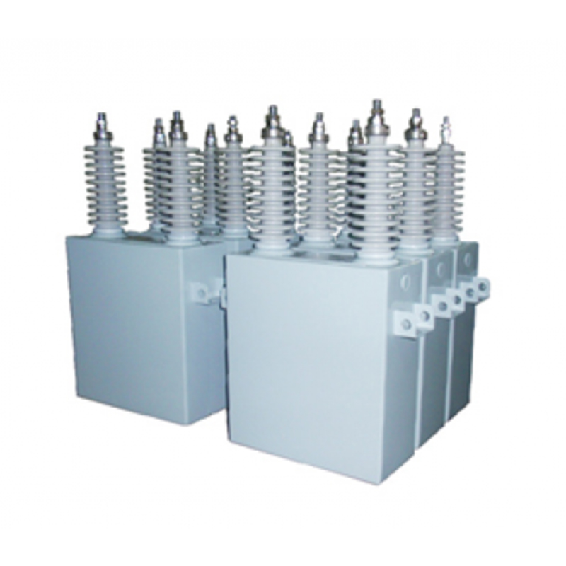
What Space Constraints Exist Inside a Compact Drive Enclosure?
Inside a small drive housing, pretty much every cubic centimeter tends to have a job to do. Power modules occupy certain areas. Control boards sit on standoffs. Bus bars run along defined paths. The DC link capacitor generally goes wherever the remaining space permits.
Some designs allocate room for a single, larger capacitor. Others scatter several smaller capacitors across the available area instead. The approach tends to change how the capacitor gets mounted and what constraints the designer ends up working with.
The flow of cooling air through the enclosure also tends to factor in here. A capacitor that sits directly in the path of air from the fan usually runs a bit cooler than one tucked behind other components. Positioning the capacitor in the airflow tends to matter because heat buildup can shorten capacitor life over time.
How Does Capacitor Orientation Affect Performance?
Terminals come in a few different arrangements, and those arrangements tend to shape how the capacitor connects to the rest of the circuit. Pin-style terminals mount to a PCB. Plate-style terminals bolt to bus bars. The style generally comes fixed with the capacitor and usually can't be changed afterward.
The route that current takes between the capacitor and the switching devices tends to add inductance along the way. A longer path tends to create more inductance, which can lead to voltage overshoot when transistors turn off. Keeping the capacitor close to the switching devices tends to cut down that path somewhat.
A few points about orientation and connection length:
- Shorter bus bar paths tend to reduce parasitic inductance
- Positioning the capacitor above or beside the bus bar affects the layout
- Terminal placement on the capacitor tends to determine how the bus bar needs to run
- Some capacitors offer terminals on opposite ends for more flexible routing
What Mechanical Fixing Methods Work for DC Link Capacitors?
Through-hole soldering tends to work for capacitors mounted to PCBs. The pins go through holes in the board and get soldered on the other side. The board generally supports the weight of the capacitor, but larger capacitors may need some extra mechanical support beyond what the pins alone provide.
Bus bars tend to provide both electrical and mechanical support for larger capacitors. Bolting the capacitor terminals directly to the bus bar tends to create a fairly solid connection. The bus bar holds the capacitor in place and carries current at the same time.
Clamping systems add another layer of mechanical security in some setups. A clamp around the body of the capacitor tends to prevent movement in higher-vibration environments. Mobile equipment and machinery with heavy motors can shake components loose over time, and clamping tends to help prevent that.
Why Thermal Management Influences Capacitor Placement
Heat tends to be one of the main factors limiting capacitor life. Ripple current flowing through the capacitor generates some internal heat. Ambient heat from nearby components tends to add to that load. The temperature inside the enclosure tends to determine roughly how long the capacitor can operate reliably.
Positioning tends to matter because some areas of the enclosure run hotter than others. A capacitor placed next to a brake resistor or a power module tends to pick up extra heat. One placed in the path of cooling air usually runs a bit cooler and tends to last longer as a result.
Designers generally have a few options for managing capacitor temperature:
- Place the capacitor upstream of heat-generating components in the airflow
- Leave clearance around the capacitor for air to circulate
- Use thermal simulation to identify hot spots in the enclosure
- Consider the capacitor's self-heating in the thermal assessment
Film capacitors used in DC link applications tend to have an upper temperature limit. Operating within that limit, the capacitor tends to reach its rated life fairly reliably. Exceeding the limit tends to accelerate aging and can lead to premature failure. Proper mounting generally helps keep the capacitor within its safer operating range.
How Does Bus Bar Design Affect Capacitor Integration
Bus bars connect the DC link capacitor to the rest of the power circuit. The layout of those bus bars determines how current flows between the capacitor and the switching devices. A well-designed bus bar keeps the connection short and direct, adding very little inductance.
Inductance in the bus bar becomes an issue when switching speeds go up. Fast-switching devices draw current in short pulses, and any inductance in the path causes voltage to spike. Those spikes stress the capacitor and the switching devices.
The loop area between the capacitor and the switches matters. A large loop captures more magnetic flux and creates more inductance. Keeping the bus bars close together or using a laminated bus bar reduces the loop area and cuts down inductance.
Bus bars also carry the ripple current that the capacitor must handle. The current passing through the bus bar heats the conductor, and that heat travels to the capacitor terminals. Bus bars with adequate cross-section carry current without excessive heating.
What Role Does the DC Link Capacitor Supplier Play in Mounting
A capacitor supplier provides more than just the component. Dimensional drawings and terminal specifications help the designer plan the mounting arrangement. The supplier's documentation shows exactly where the terminals sit and how much clearance the capacitor needs.
Some suppliers offer customization for high-volume platform designs. Adjusting terminal positions, changing the case shape, or adding mounting features can simplify integration. Early engagement with the supplier gives the designer more options.
Technical support from a DC Link Capacitor Supplier often includes application guidance. The supplier can advise on terminal torque, bus bar design, and thermal management. That advice saves time during the development phase.
What Are Common Mounting Mistakes to Avoid
Terminal orientation causes some of the more common problems. A capacitor with terminals on the side fits differently than one with terminals on top. Choosing the wrong orientation forces changes to the bus bar or the PCB layout.
Clearance for thermal expansion often gets overlooked. Capacitors expand and contract as temperature changes. A tight fit that does not accommodate that movement can stress the terminals or the mounting hardware.
Vibration creates problems in mobile applications. A capacitor that is not secured properly can work loose over time. The terminals or the bus bar take the stress, and connections can fail.
Some common mounting errors:
- Installing the capacitor too close to a heat-generating component
- Failing to allow clearance for insertion and removal tools
- Under-tightening or over-tightening terminal bolts
- Leaving no space for thermal expansion
How Can Thermal Simulation Improve Mounting Decisions
Simulation tools predict temperature distribution inside the enclosure before any hardware gets built. The designer can test different capacitor positions virtually and see which one keeps the capacitor coolest. The approach saves time and avoids costly prototypes.
Simulation also reveals hot spots that might not be obvious from the layout. A capacitor that looks fine on the drawing board may sit in a pocket of stagnant air that causes overheating. Simulation catches those issues early.
A DC Link Capacitor Supplier may offer thermal data for simulation. The data includes the capacitor's thermal resistance and power loss characteristics. Using that data in the simulation gives more accurate results.
| Consideration | Potential Issue if Ignored | How to Address |
|---|---|---|
| Terminal orientation | Incorrect connection routing | Review datasheet before layout |
| Thermal expansion | Stress on terminals or solder joints | Allow clearance for movement |
| Vibration | Loosening of connections in mobile applications | Use clamps or brackets for support |
| Bus bar inductance | Voltage overshoot during switching | Minimize loop area, use laminated bus bars |
| Airflow access | Overheating from restricted air circulation | Position in cooling path, avoid blockage |
What Practical Steps Ensure Reliable Capacitor Mounting
Planning the capacitor placement early in the design process prevents problems later. Leaving the position until the final stages of layout usually forces compromises. An early decision gives the designer room to optimise the bus bar, airflow, and mechanical support.
Service access also deserves attention. A capacitor that sits buried under other components may be difficult to reach for inspection or replacement. The mounting arrangement should allow access when needed.
Mechanical clearance and electrical clearance must both be verified. The capacitor should not touch other components or the enclosure walls. The creepage and clearance distances required for the operating voltage must be maintained.
Testing under worst-case operating conditions confirms the mounting arrangement works. Applying full load and monitoring the capacitor temperature reveals whether the thermal design is adequate. Adjusting the mounting or the airflow based on test results leads to a reliable final design.
A few steps that lead to reliable mounting:
- Place the capacitor early in the layout process
- Verify clearance from other components and the enclosure
- Consider service access for eventual replacement
- Use clamps or brackets in high-vibration applications
- Monitor temperature during prototype testing


Recommended Products
The variety of models, to meet the development needs of various regions in the world.
Copyright © Shanghai Yongjin Electric Technology Co.,Ltd.

China Power Quality Solutions Supplier