


 English
 中文简体
中文简体 русский
 Español
 عربى
عربى
Industry News
Which Capacitor Bank Configuration Fits Your Industrial Load Profile
Industrial electrical loads rarely behave in exactly the same way throughout an operating day. A motor may run for several hours and then stop. Heating equipment can cycle according to production needs. Ventilation equipment may operate only during certain periods, while other machines remain active for longer periods.
These differences affect reactive power demand and, in turn, the way a Capacitor Bank needs to be configured. A fixed arrangement may suit a relatively stable load, while a changing load may require several compensation stages that can be switched according to operating conditions.
Load type also matters. Inductive equipment can create a demand for reactive power, while capacitive equipment behaves differently. A mixed industrial installation may contain both conditions at the same time.
A practical assessment starts with three questions:
- What type of electrical load is connected?
- How does the load change during normal operation?
- When does the reactive power demand become significant?
How Does The Load Type Affect Reactive Power Demand
Industrial loads can be broadly viewed as inductive, capacitive, or mixed. Each condition creates a different relationship between active power and reactive power.
Inductive loads are common in equipment that uses magnetic fields during operation. Motors and transformers are typical examples. Their operation can create reactive power demand in addition to the useful power consumed by the equipment.
Capacitive loads behave in the opposite direction from an electrical compensation perspective. Capacitors can supply reactive power rather than demand it. When a system already contains significant capacitive behavior, adding further capacitance without checking the existing condition can create an imbalance.
Mixed loads are common in actual factories. A production area may contain motors, lighting equipment, heating systems, control equipment, and other electrical devices. Some may create inductive demand while others have a different electrical behavior.
| Load Type | Typical Electrical Behavior | Configuration Consideration |
|---|---|---|
| Inductive | Creates reactive power demand | Compensation may be required |
| Capacitive | Supplies reactive power | Additional capacitance needs careful evaluation |
| Mixed | Different loads operate together | Overall operating condition needs to be assessed |
| Changing load | Demand varies with equipment status | Adjustable compensation can be useful |
How Should Capacity Be Judged For Inductive Loads
Inductive loads require attention because reactive power demand can change with operating conditions. A motor operating under a substantial mechanical load may have a different electrical profile from the same motor running with a lighter load.
Capacity selection should begin with the actual reactive power requirement rather than the physical size or quantity of connected machines. Equipment ratings can provide useful background information, but they do not always represent the condition during normal operation.
Several factors can affect the required compensation:
- Motor loading
- Transformer operation
- Equipment running time
- Simultaneous operation of several machines
- Changes between production stages
- Equipment that starts or stops frequently
A stable industrial process may produce a relatively predictable reactive demand. In such a situation, a fixed capacitor arrangement can sometimes match the operating pattern because the compensation requirement changes only slightly.
A variable process needs a different approach. If large inductive equipment is active during one operating period and inactive during another, a permanently connected capacitor can remain in the circuit when the reactive demand has fallen.
That condition can create overcompensation. Instead of improving the balance of the electrical system, excessive capacitance can push the system toward an undesirable operating condition.
Capacity should also leave room for normal operating variation. Selecting a size based only on a single operating point can make the configuration less suitable when production conditions change.
What Changes When The Load Is Mainly Capacitive
A capacitive load requires a different way of looking at compensation. When capacitance is already present in the electrical system, additional capacitor capacity may not be necessary and can create an excessive capacitive condition.
The source of existing capacitance may come from several parts of an industrial installation. Power conversion equipment, long electrical connections, correction equipment, and other components can contribute to the overall electrical behavior.
The important point is that compensation should respond to the actual condition of the system. A calculation based only on inductive equipment can miss an existing capacitive contribution.
Signs that deserve attention include:
- Reactive power changing direction during different operating periods
- Electrical conditions changing after equipment is switched off
- Capacitive behavior appearing when inductive machines are inactive
- Different sections of a facility showing different load characteristics
A facility with a large number of motors may appear to have a clear inductive requirement, yet the electrical condition can change after those motors stop. If capacitor stages remain connected during that period, the compensation level may no longer match the load.
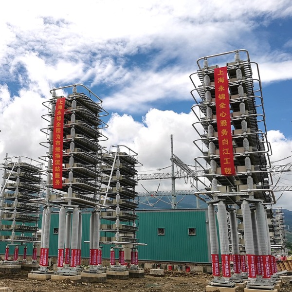
A Capacitor Bank used in such an environment needs a configuration that reflects the actual operating state. Switching capability can become relevant when the reactive demand changes rather than remaining constant.
How Should Mixed Loads Be Evaluated
Mixed loads require a broader view because several electrical behaviors can exist at the same time. A factory floor may have motors operating alongside heating equipment, lighting systems, ventilation units, and other electrical loads.
The combined load does not simply equal the sum of the equipment labels. Each device may operate at a different time and under a different load condition. A production line may also change its electrical demand as machines move between operating stages.
A useful assessment separates the facility into practical operating groups.
Continuous loads
Equipment that remains active for long periods can form a relatively stable part of the electrical profile.
Intermittent loads
Machines that start and stop according to production tasks can create noticeable changes in reactive demand.
Cyclic loads
Heating, cooling, ventilation, and similar systems may switch between operating states during normal operation.
Occasional loads
Large machines used only during particular production activities may have little influence during other periods.
The relationship between these groups affects capacitor selection. A fixed configuration may work when the combined inductive demand remains reasonably stable. A stepped arrangement becomes more relevant when the combined demand moves between different operating states.
A mixed load also makes capacity planning more dependent on actual operation. Simply adding the reactive requirements of every connected machine may produce a capacity that does not match the conditions under which the equipment normally runs.
A more practical assessment considers which machines operate together, how long they remain active, and how the electrical load changes when individual groups start or stop. These operating patterns provide a clearer basis for deciding how much compensation is needed and how that compensation should be divided into stages.
When Does A Fixed Capacitor Bank Fit A Stable Load
A fixed capacitor arrangement is easier to consider when the electrical load follows a relatively stable pattern. If a large motor or a continuous industrial process remains active for long periods, the reactive power demand may change only within a limited range during normal operation.
The key condition is stability rather than simply the size of the connected equipment. A large motor that operates under changing conditions may still require adjustable compensation, while several steady loads may work with a simpler arrangement.
Before using a fixed configuration, several points should be checked:
- Whether the main inductive loads remain active for long periods
- Whether the reactive demand changes significantly during normal operation
- Whether large machines are regularly switched off
- Whether capacitive behavior appears during low‑load periods
- Whether the expected operating pattern remains reasonably consistent
The possibility of overcompensation needs attention. When an inductive machine stops while a fixed capacitor remains connected, the amount of capacitance may no longer match the active load.
A fixed Capacitor Bank is therefore closely tied to the actual load curve. A stable electrical environment can make a fixed arrangement practical, while a load that moves through several operating states may require a configuration that can adjust.
When Are Two Step Capacitor Configurations More Suitable
A two‑step arrangement divides the compensation capacity into separate sections. Instead of connecting the entire capacitor capacity at once, individual sections can be switched according to the reactive demand.
This approach can suit an industrial installation where the load moves between a lower operating state and a higher operating state. When only part of the inductive equipment is active, one compensation section can be connected. Additional capacity can be added when more equipment starts operating.
- Lower demand — only a smaller compensation section remains connected.
- Rising demand — another section can be added.
- Falling demand — an additional section can be disconnected
- Low‑load condition — unnecessary compensation can be removed.
The value of this arrangement comes from matching the compensation level with the load instead of keeping a fixed amount connected throughout the operating period.
It can be useful in facilities where production equipment follows a relatively clear operating pattern. For example, a group of motors may operate during one production stage and a larger group may operate during another. Two separate compensation sections can follow these changes more closely than a single fixed section.
The switching method also needs to suit the behavior of the load. Frequent equipment changes may require a control arrangement that can respond without creating unnecessary switching activity.
How Does A Multi Step Capacitor Bank Handle Changing Loads
Some industrial facilities have a load pattern that changes repeatedly during normal operation. Production schedules can alter machine activity, ventilation equipment can change its operating state, and motors can start or stop at different points in the process.
A multi‑step Capacitor Bank divides the total compensation into several smaller stages. Each stage can be connected or disconnected as the reactive demand changes.
This arrangement provides finer adjustment than a single fixed section or a simple two‑step configuration. Smaller stages can help avoid a large change in compensation when the load changes only slightly.
A multi‑stage system can be considered when:
- Several groups of machines operate at different times
- Production conditions change during the operating period
- Motor starting creates noticeable changes in electrical demand
- Ventilation or cooling equipment cycles regularly
- The facility contains a mixture of continuous and intermittent loads
The control system needs to recognize the electrical condition before deciding which stages should be connected. A poorly matched stage size can create unnecessary switching or leave the system with too much or too little compensation.
Stage size is therefore part of the configuration decision. Large stages may suit a load that changes in broad steps, while smaller stages can provide a closer response when the load moves gradually.
How Should Capacitor Capacity Match The Actual Load
Capacity selection should begin with measured or calculated reactive power demand during real operating conditions. A connected equipment list can help identify potential sources of inductive demand, but it does not show how those machines behave together throughout the operating period.
A useful assessment can separate the electrical load into several conditions:
- Normal production — equipment operating under routine conditions
- Reduced production — part of the equipment remains inactive
- Heavy production — several inductive machines operate together
- Start and stop periods — electrical demand changes as equipment enters or leaves service
- Low‑load periods — only a small part of the facility remains active
The required compensation can then be considered across these conditions rather than at a single operating point.
A suitable capacity also needs some allowance for changes in the production process. Equipment may be added, removed, replaced, or operated differently over time. A configuration with no room for adjustment can become difficult to manage when the load profile changes.
Capacity should also be checked against the risk of overcompensation. A larger capacitor rating does not automatically produce a better electrical condition. When the actual inductive demand is low, excessive capacitance can create an unwanted capacitive condition.
For mixed industrial loads, the practical target is a compensation level that follows the real reactive demand without repeatedly moving between excessive and insufficient compensation.
Where Should The Capacitor Bank Be Installed
Installation location affects both electrical performance and practical maintenance. A capacitor assembly can be installed near the main distribution section or closer to a group of major inductive loads, depending on the electrical structure of the facility.
A location near the main distribution point can make inspection and maintenance more straightforward. It can also allow several load groups to share a common compensation arrangement.
Placing compensation closer to a large inductive load can shorten the local path between the load and the compensation equipment. This approach may be useful when a particular machine group creates a substantial and relatively predictable reactive demand.
Several installation conditions need to be considered:
- Available cabinet or panel space
- Access for inspection and maintenance
- Heat generated by nearby electrical equipment
- Length and routing of connecting conductors
- Distance from major inductive loads
- Protection and isolation requirements
- Possibility of future changes to the load arrangement
The installation environment also influences the physical arrangement of the capacitor stages. Adequate space around components helps with inspection and heat movement, while secure mounting reduces mechanical stress on electrical connections.
A Capacitor Bank should fit the actual electrical and physical conditions of the facility. Load type provides the starting point, while load variation determines whether fixed or adjustable compensation is appropriate. Capacity then needs to follow the reactive demand observed during real operating conditions, with installation location considered as part of the complete configuration.
Recommended Products
The variety of models, to meet the development needs of various regions in the world.
Copyright © Shanghai Yongjin Electric Technology Co.,Ltd.

China Power Quality Solutions Supplier