English
 中文简体
中文简体 русский
 Español
 عربى
عربى
Industry News
Home / News / Industry News / Why Do High Voltage Capacitors Fail After Installation? Common Causes Explained
Why Do High Voltage Capacitors Fail After Installation? Common Causes Explained
Capacitors high voltage are standard pieces of gear across industrial power systems for handling power factor correction, voltage support, line compensation, and capacitor bank layouts. When you select them right, install them properly, and keep up with protection and maintenance, these units can run reliably for long stretches. But if a capacitor fails right after installation, it usually points to system issues rather than a bad component out of the box.
More often than not, early failures tie back to messy field conditions, mismatched system parameters, sloppy wiring habits, bad protection configurations, harmonics, high heat, or skipping basic commissioning steps. For electrical contractors, EPC crews, system builders, and plant engineers, getting a handle on these variables is a big deal before flipping the main switch on a new build.
This field guide breaks down the usual culprits behind early high voltage capacitor failures and maps out practical checkpoints across industrial power networks.
What Causes a High Voltage Capacitor to Fail After Installation?
A high voltage capacitor can pop due to electrical, thermal, mechanical, environmental, or installation-related stress. Certain issues show up the exact second you energize the system, while other problems cook over time as the internal elements handle non-stop electrical and heat stress.
Common culprits include:
Your starting point for troubleshooting is figuring out if the failure is just a one-off fluke or if it's taking out multiple units in the same cabinet. If you keep losing bits, you are dealing with a broader system-level problem.
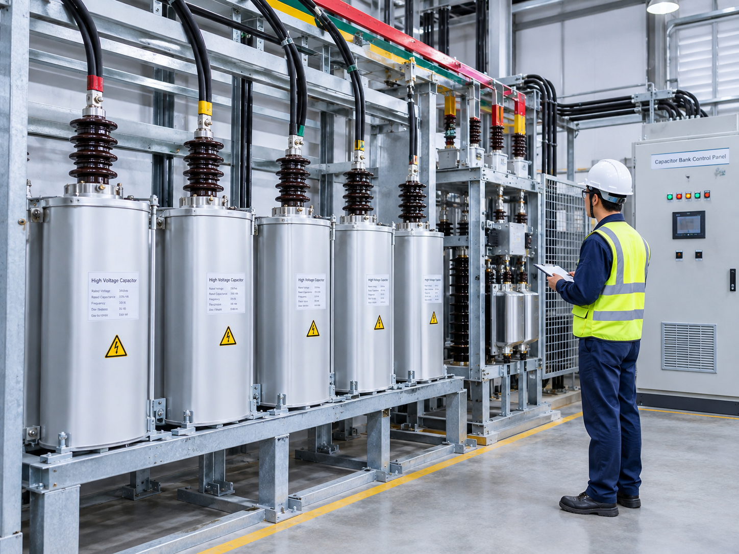
Incorrect Voltage Rating or Capacitor Selection
One of the most basic ways to kill a bit early is picking a capacitor that doesn't actually match the real-world traits of your electrical system.
The rated voltage on the label needs to handle the true running voltage and any regular spikes expected on the line. Field engineers also have to double-check total capacitance, line frequency, actual KVAR needs, wiring layouts, and daily power fluctuations.
For instance, chucking a capacitor into a network that runs hot with persistent overvoltage puts way too much electrical stress on the internals. Even if nominal readings look fine on paper, weird field operations can change the stress loading overnight.
Before installation, verify:
| Parameter | What to Check |
|---|---|
| System voltage | Actual operating voltage and allowable variation |
| Capacitor rated voltage | Compatibility with the application |
| Capacitance | Required reactive compensation |
| Frequency | System frequency and capacitor specification |
| Connection | Correct configuration and phase arrangement |
| Operating temperature | Expected ambient and equipment temperature |
| Harmonics | Presence of significant harmonic distortion |
| Protection | Compatibility with the capacitor and system |
Always check your physical tool specs against the manufacturer's technical sheets and the actual plant network.
Harmonics Can Put Additional Stress on Capacitors
Harmonic distortion is a massive headache in modern industrial power systems. Variable frequency drives, rectifiers, heavy UPS gear, switching supplies, and other nonlinear loads constantly pump harmonic currents back into the local grid.
A standard capacitor bank can interact with these distorted frequencies and, under the right conditions, trigger a nasty resonance loop. This spikes the current traveling through the capacitor, leading to rapid heating and severe electrical stress.
Signs of a harmonic-related capacitor issue include:
When you are burning through replacement capacitors, just slapping a fresh unit in the tray isn't going to fix the core problem. Bringing in a power quality analyzer can help you figure out if harmonic distortion or resonance is driving the failures.
For heavy industrial plants packed with nonlinear drives, handling harmonic analysis during the layout phase is a smart move.
Excessive Temperature Reduces Service Life
Ambient heat plays a massive role in how well a capacitor survives. If you mount a capacitor inside a stuffy enclosure with terrible ventilation, it is going to run way hotter than intended.
That heat usually builds up from a mix of sources:
A working capacitor bank needs proper spacing and airflow matching its design sheets. Keep the local environment in mind when figuring out your enclosure setup and choosing your hardware.
If a bunch of capacitors in the same rack are cooking, look at the overall ventilation of the room or cabinet rather than blaming individual units.
Loose Connections and Incorrect Wiring
Sloppy electrical connections are a highly common source of early failures right after commissioning.
A loose terminal bolt cranks up contact resistance, causing localized heating that destroys the wire connection and introduces extra electrical stress over time.
Incorrect wiring jobs can also cause severe phase imbalances or prevent the entire capacitor bank from running the way it was engineered.
During the commissioning checks, installers need to verify:
Torque specs should match the manufacturer’s documentation to the letter. You should also check these connections during regular maintenance cycles, especially in plants with high vibration or heavy thermal cycling.
Switching Transients and Inrush Current
Capacitors can pull a massive hit of transient current the exact second you energize them. In a multi-stage bank layout, stepping in a fresh stage can also play havoc with units that are already live on the bus.
These brutal switching cycles put a ton of mechanical and electrical stress on contactors, switches, fuses, supply cables, and the capacitor elements themselves.
The problem gets way worse when:
Make sure you choose proper capacitor switching hardware and control loops based on the system design. On larger industrial sites, engineers should analyze switching transients as part of the initial startup process.
Inadequate Protection Can Allow Damage to Continue
A solid high voltage capacitor setup requires proper protection based on your exact layout and application.
A normal protection scheme handles combinations of:
The right protection setup depends entirely on the style of capacitor, bank layout, voltage level, and the rest of the electrical grid.
If a capacitor pops repeatedly but the breakers never trip, you need to audit your protection settings and device coordination. Protection isn't a detail you figure out later; it has to be cooked straight into the initial design.
Insufficient Discharge After Switching
A capacitor acts as a battery, holding onto dangerous electrical energy even after you isolate it from the grid. Because of that, a reliable discharge path is an absolute requirement on any high voltage setup.
If the residual voltage isn't dropped down to a safe level before technicians open the cabinet, it creates a fatal electrical hazard.
The discharge circuit must be mapped out and tested according to local safety rules. Maintenance guys should never assume a isolated capacitor is safe to touch.
A proper lock-out procedure means isolating the gear, verifying zero voltage with a meter, and waiting the full discharge duration specified by the builder.
Installation Environment Can Affect Capacitor Performance
The local environment can ruin a capacitor setup, especially in outdoor or heavy industrial spaces.
Keep an eye out for factors like:
For outdoor setups, you have to look closely at cabinet seals, insulation coordination, weather exposure, and quick maintenance access during the layout phase.
A capacitor built to survive a clean room will fail rapidly if you drop it into a dirty mill without changing the enclosure protection.
Mechanical Damage and Transportation Issues
Not every single early failure traces back to an electrical mistake.
Capacitors and internal bits frequently take a beating during shipping, uncrating, rigging, or physical installation. Mechanical damage like that can stay hidden until you energize the system.
Before turning the power on, walk the floor and look for:
If you spot any physical damage, pause the job and investigate before hooking the capacitor up to the line.
Capacitor Bank Configuration Problems
In major industrial systems, capacitors usually run as a group inside a larger bank layout. How you configure that bank changes how each individual canister behaves.
Problems trigger fast when the total number of stages, wiring layout, switching order, or protection settings don't match the engineering print.
Engineers need to audit the whole bank setup rather than just swapping out a single dead capacitor.
Key checks include:
| Area | Inspection Focus |
|---|---|
| Bank configuration | Correct number and arrangement of capacitor units |
| Phase balance | Comparable operating conditions between phases |
| Switching sequence | Appropriate stage switching |
| Protection | Correct settings and coordination |
| Harmonics | System distortion and resonance conditions |
| Ventilation | Adequate heat dissipation |
| Connections | Secure and correctly configured wiring |
| Maintenance access | Safe access for inspection and servicing |
How to Troubleshoot a High Voltage Capacitor That Has Failed
When a brand-new capacitor pops right away, don't just grab a replacement block and plug it in.
Run a clean investigation to find out what's actually killing the tool.
Step 1: Isolate the Equipment
Follow your site's LOTO and electrical safety steps to dead-check the bank before opening the doors. Only qualified high-voltage techs should be turning wrenches here.
Step 2: Record Operating Conditions
Grab all the historical data you can find regarding:
This data lets you piece together whether the failure happened during a quiet shift or right during a brutal switching cycle or power spike.
Step 3: Inspect the Physical Condition
Walk the bank and check for scorch marks, fluid leaks, dented casings, loose terminal posts, discoloration, or fried insulation.
Step 4: Check the Complete System
Trace the wiring, audit the breakers, check contactors, clear out ventilation fans, and verify grounding lines.
Step 5: Evaluate Power Quality
If you keep losing capacitors, set up a power quality meter to track harmonic distortion, line sags, and voltage spikes.
Step 6: Compare Results With Manufacturer Requirements
Cross-reference your field readings with the manufacturer's spec sheets and the core project blueprints.
How to Prevent Premature High Voltage Capacitor Failure
Stopping a failure starts long before the hardware ever lands at your loading dock.
A practical field plan looks like this:
On major industrial builds, looping in the technical support team during the design phase saves a ton of compatibility headaches later down the road.
What Engineers Should Check Before Energizing a New Capacitor
Run through a quick pre-power checklist to avoid stupid commissioning mistakes:
Electrical
Mechanical
Environmental
System
Your exact field tests should line up with the manual, site parameters, national electrical codes, and your company's own engineering safety policies.
Frequently Asked Questions About High Voltage Capacitor Installation
Why does a high voltage capacitor fail shortly after installation?
Early failure usually boils down to overvoltage issues, high running heat, harmonic current stress, switching spikes, sloppy wiring, mismatched protection settings, or a bad application fit. If you keep losing units, step back and look at the broader grid.
Can harmonics damage a high voltage capacitor?
Absolutely. Harmonic currents increase the current draw and heat loading inside the tool, and certain grid layouts can trigger a brutal resonance loop. Always map out harmonic profiles when building an industrial capacitor bank.
Does a capacitor need protection after installation?
Yes, high voltage setups require a proper protection layout tailored to the gear and system design. Your exact mix of fuses and breakers depends on line voltage, bank sizing, and utility guidelines.
What should be checked after installing a high voltage capacitor?
Techs should verify terminal torque, actual line voltage, breaker settings, grounding lines, contactor sequencing, cabinet ventilation, and general physical condition against the manual.
Why do multiple capacitors fail in the same installation?
Losing a bunch of units points straight to a common system problem, like persistent overvoltage, harmonic loops, bad ventilation, switching spikes, mismatched wiring configurations, or improper protection settings. Swapping individual capacitors without fixing the core system issue is a waste of time.
Selecting High Voltage Capacitors for Industrial Applications
For commercial builds, select your capacitors based on the complete application environment rather than buying on product names alone. Grid voltage, total capacitance, line frequency, load behavior, harmonics, room conditions, mounting styles, and breaker setups all dictate whether a capacitor survives or dies.
Your equipment supplier should be able to hand over clear product manuals, installation steps, footprint drawings, electrical parameters, and application notes for your specific model.
On EPC contracts and large industrial networks, getting technical lines open early aligns your capacitor specs with the main bank hardware, switchgear, protection loops, and field realities.
When a new high voltage capacitor blows right after startup, the dead component is rarely the whole story. Looking at the complete electrical network and environmental setup gives you a proper diagnosis and stops you from burning through the next batch of gear.
The variety of models, to meet the development needs of various regions in the world.
Copyright © Shanghai Yongjin Electric Technology Co.,Ltd.

China Power Quality Solutions Supplier