 English
 中文简体
中文简体 русский
 Español
 عربى
عربى
Industry News
Can Low Voltage Capacitor Be Used In High Power Applications
Low voltage capacitor components often appear in circuit layouts where electrical activity stays calm and controlled. In everyday electronics, not every section carries heavy energy. Some parts only pass signals, adjust timing, or smooth small changes that happen during switching.
In those lighter zones, a low voltage capacitor usually behaves like a stabilizer. It reacts to small fluctuations that appear when a device turns on, shifts mode, or sends weak signals through a line. Without that small buffering effect, nearby parts may pick up noise or uneven movement in signal flow.
In real use, its presence is often connected with:
- smoothing small jumps in signal paths
- keeping timing sections steady during switching
- reducing minor electrical noise in control areas
- supporting stable behavior in low-energy zones
Most of the time, it sits in the background of a circuit, quietly handling small irregularities that are easy to overlook but still affect overall stability.
A low voltage capacitor is not defined by size alone. The internal structure decides how it behaves when electricity passes through it. Inside the component, two conductive layers face each other, separated by a dielectric layer that resists electrical stress.
That dielectric layer is the key boundary. It holds charge separation and controls how much voltage the structure can tolerate before instability begins.
Inside the structure, several simple roles work together:
- conductive layers store and release electrical charge
- dielectric layer resists breakdown from voltage stress
- spacing between layers controls internal stability
- structure maintains balance during charge cycles
In practical environments, this kind of capacitor behaves calmly in low-stress sections. Once conditions become more demanding, the internal balance starts feeling pressure from stronger electrical forces.
How High Power Environments Differ From Low Voltage Circuits
High power environments do not behave like small signal sections. The difference is not only in voltage level, but in how long and how intensely energy flows through the system.
In low voltage areas, the focus stays on signals and control. Changes are small and usually predictable. In high power sections, energy flow becomes heavier, and components nearby must deal with heat, continuous load, and stronger electrical movement.
Typical differences in real operation:
- higher current flowing for longer periods
- stronger heat appearing during continuous use
- more stress across connected components
- less tolerance for small mismatches in design
In many systems, both environments exist together. One part manages control signals while another handles energy delivery. The separation between these zones becomes important for stability.
What Happens When Low Voltage Capacitor Is Exposed To High Power Demand
When a low voltage capacitor ends up in a high power section, stress begins to build slowly inside the structure. At first, nothing looks unusual. The component still works, still responds, still performs its basic role.
Over time, internal conditions start to change. Electrical stress inside the dielectric layer increases. Heat may build up during repeated operation. The internal balance becomes harder to maintain.
What often develops over time:
- gradual rise in internal temperature
- increased strain on dielectric separation layer
- slower response during rapid changes
- reduced stability during long operation cycles
The change is usually gradual, not sudden. That makes early signs harder to notice in real circuits until behavior begins to drift from expected performance.
Why Circuit Layout Sometimes Still Uses Low Voltage Capacitor In Specific Areas
Modern circuit design often divides systems into sections. Not every part needs to handle strong electrical load. Some areas only deal with information flow, switching signals, or timing coordination.
In those controlled areas, low voltage capacitor components can still be useful. The goal is not energy handling, but stability within a limited range of activity.
Typical placement situations include:
- control signal smoothing zones
- timing adjustment paths in low-energy circuits
- noise reduction near input lines
- isolated signal processing sections
The separation between power and control sections allows different components to work within suitable conditions instead of sharing the same stress level.
How Load Distribution Changes Capacitor Behavior In Real Systems
Load inside a circuit does not always spread evenly. Some areas carry more activity, while others remain relatively quiet. This uneven distribution changes how stress appears across components.
A low voltage capacitor reacts differently depending on where it sits in that structure. Even small shifts in load pattern can influence stability over time.
| Load Situation | Circuit Behavior | Practical Result |
|---|---|---|
| Balanced activity | stable operation | predictable response |
| uneven load zones | local stress build-up | gradual drift in performance |
| fluctuating demand | irregular signal movement | timing variation |
| continuous load pressure | long-term strain | reduced stability |
What Engineers Check Before Using Low Voltage Capacitor In A System
Before selecting a low voltage capacitor for a circuit, several practical conditions are usually considered. Voltage rating is only one part of the picture. Real operation involves heat, time, and repeated electrical changes.
Key checks often include:
- temperature behavior during steady operation
- stress level in surrounding circuit section
- compatibility with signal or control path role
- expected duration of continuous activity
Even in low-energy zones, heat can slowly accumulate depending on surrounding conditions. That slow buildup affects long-term stability more than short bursts of activity.
How Risk Is Viewed In Mixed Voltage Circuit Systems
In systems where low voltage and high power zones exist together, design attention focuses on interaction between sections rather than isolated components. A capacitor may behave differently depending on how energy flows through nearby paths.
Observation in real systems often includes:
- stability during switching between circuit states
- response under changing electrical load
- behavior across long operating periods
- influence from nearby high power activity
Instead of looking at a single point in time, engineers often watch how behavior changes across repeated cycles. Small variations in response can reveal how well each section stays within its intended range.
What Role Low Voltage Capacitor Solutions Play In System Optimization
In many mixed circuits, low voltage capacitor solutions are not placed by chance. Their use usually depends on where small electrical changes need support without disturbing stronger power sections. A control board inside a larger device may carry weak signals, timing paths, and noise-sensitive lines, while another section handles heavier load movement. Separating those functions allows each part to work under conditions that match its own electrical behavior.
A low voltage capacitor in that setting often supports a quieter part of the circuit. It may smooth a small signal line, keep a sensing path more stable, or reduce the effect of quick switching changes. The goal is not to handle large energy transfer. The goal is to keep small electrical movement steady enough for nearby components to read correctly.
In practical systems, placement matters a great deal:
- near signal inputs where small disturbances matter
- beside control sections that need stable timing
- in filtered paths where small fluctuations need buffering
- away from heat-heavy power zones that create stronger stress
Low voltage capacitor solutions work well when the circuit is divided with purpose. A simple board may look compact from the outside, yet inside it often contains several different electrical climates. Some zones stay calm. Others stay active. A component performs better when its role matches the zone where it is used.
How Material Composition Influences Voltage Handling Capability
The internal material of a capacitor decides how well it can tolerate stress. The dielectric layer is especially important because it separates the conductive parts and keeps charge from breaking through too easily. A small difference in material behavior can change how the part responds during long use.
Material choice affects several practical points:
- how much voltage the dielectric can resist
- how quickly heat affects internal stability
- how the structure changes under repeated charge cycles
- how much stress the part can absorb before drifting from normal behavior
In a low voltage capacitor, the structure is built for controlled conditions. That means the internal material is not meant to face high load all the time. When the material stays within its intended range, it keeps a stable shape of behavior. When stress rises too high, the internal balance begins to weaken little by little.
Real-world response often shows up in stages:
The material itself does not change visibly in a short moment. It changes through repeated pressure from the circuit environment.
| Internal Condition | Material Response | Circuit Effect |
|---|---|---|
| steady low stress | stable dielectric behavior | smooth performance |
| rising temperature | gradual material strain | slight drift in response |
| repeated overload | weakened insulation margin | unstable operation |
| long exposure | internal degradation | reduced reliability |
What Design Mistakes Occur When Voltage Rating Is Ignored
Ignoring voltage rating causes problems that often appear slowly rather than all at once. A low voltage capacitor may still seem to function after being placed in a stronger section, which can create a false sense of security. The system may run for a while, then begin showing unstable behavior when heat or load continues to rise.
A common mistake is assuming that storage capacity alone defines suitability. That is not how capacitor selection works. Voltage rating sets the boundary for safe operation. When that boundary is crossed, the dielectric layer is placed under stronger stress than it was built to handle.
Typical mistakes include:
- placing the part in a section with higher stress than intended
- assuming short-term operation means safe long-term use
- overlooking repeated heat buildup near the component
- mixing control-section parts into stronger power paths
What tends to happen next is gradual. Performance may drift, the circuit may become less stable, and the component may age faster than expected. In some systems, failure does not show up as a sudden event. It appears as a slow loss of predictable behavior.
How Modern Electrical Systems Separate Voltage Zones
Modern systems often divide electrical work into zones with different roles. One zone may deal with power transfer, while another handles signals, timing, and control. That separation allows each section to stay within its own stress range.
A low voltage capacitor often belongs in the quieter side of that structure. It can support filtering or stability in areas where the current stays light and voltage swings remain controlled. A different component type may be used in power sections where the load is larger and the heat pattern is stronger.
A simple zone view can look like this:
- signal zone for sensing and timing
- control zone for switching and minor adjustments
- power zone for energy delivery and heavy load
- isolation zone for keeping noise from moving across sections
This separation helps the circuit behave more predictably. It also reduces the chance that a low voltage part gets pushed into a role it was never meant to take.
Why Low Voltage Capacitor Choices Depend On System Structure
The same capacitor may perform well in one system and poorly in another. The reason often lies in the surrounding structure, not only in the component itself. Placement, load pattern, temperature, and switching rhythm all shape how the part behaves.
In a simple system, the current path may stay calm enough for a low voltage capacitor to work without issue. In a more active system, nearby power sections may create conditions that slowly stress the dielectric layer. That is why engineers often look at the full circuit layout instead of a single component label.
Important structure-related factors include:
- whether the part sits near heat-producing sections
- whether nearby load changes happen quickly or slowly
- whether the circuit path is for control or power delivery
- whether the part can stay within its intended voltage zone
In practice, the question is not only whether a component can fit physically. The more important question is whether the surrounding circuit allows it to stay within its safe operating range.
How Risk Is Viewed In Mixed Voltage Circuit Systems
Mixed voltage systems need careful separation because different areas create different kinds of stress. A component in the wrong place may experience conditions that look manageable at first, then begin to drift as use continues.
Risk evaluation often focuses on practical behavior:
- how the capacitor reacts during repeated switching
- whether heat builds near the placement zone
- how nearby current movement changes with load
- whether the circuit stays stable over longer operation periods
A low voltage capacitor used in a mixed system may work well in a control branch while remaining far from stronger load paths. That kind of placement lowers risk. When placement is unclear or loose, stress can spread into the wrong zone and change performance over time.
How Engineers Think About Low Voltage Capacitor Solutions In Real Systems
Low voltage capacitor solutions are often part of a larger design decision. They are not selected only for their part size or rating. Their role is defined by how they fit into the circuit structure and how much electrical stress they will face in daily use.
In a practical engineering setting, the selection process usually considers:
- the type of signal passing through the path
- the amount of heat expected during operation
- the stability needed in the control section
- the surrounding components and their load behavior
A well-placed capacitor can support stability in the right area. A poorly placed one can age quickly or behave unpredictably. That difference often comes down to matching component behavior with circuit role.
A low voltage capacitor can belong in a system that includes high power sections, yet that does not mean it can handle those stronger sections directly. The key lies in structure. When the circuit divides power and control into separate zones, the component can still support filtering or timing in the lower-stress side.
In that sense, the answer is not a simple yes or no. It depends on where the component sits, what kind of load it sees, and how the circuit manages heat and voltage boundaries. Careful design keeps the component inside its useful range, while poor placement pushes it into stress conditions that shorten reliable operation.
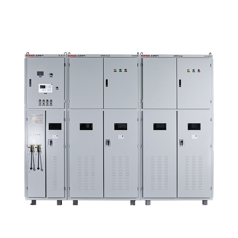

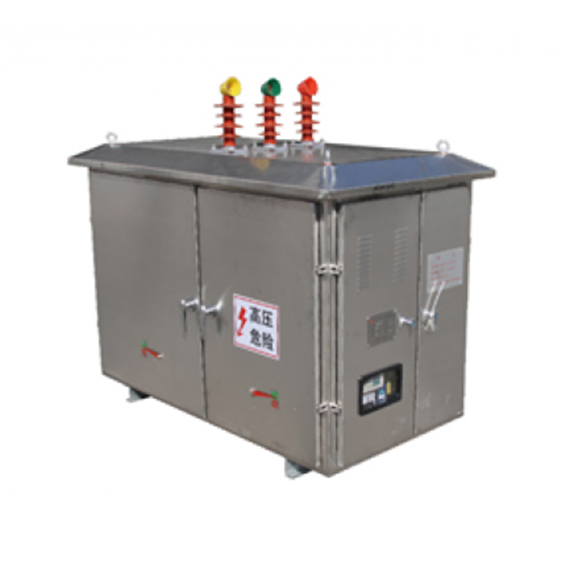
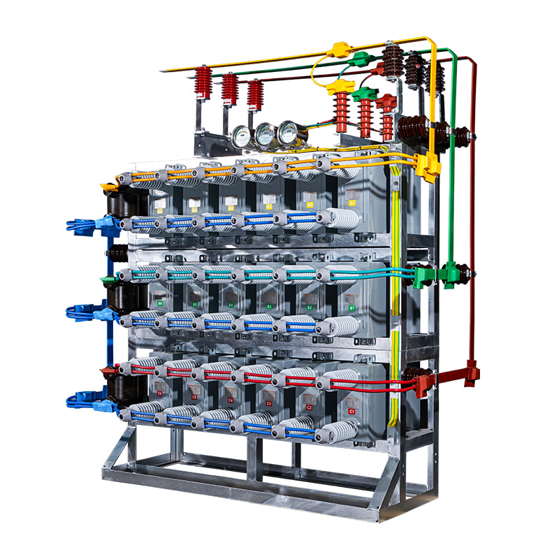
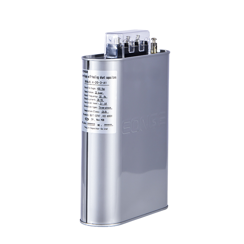
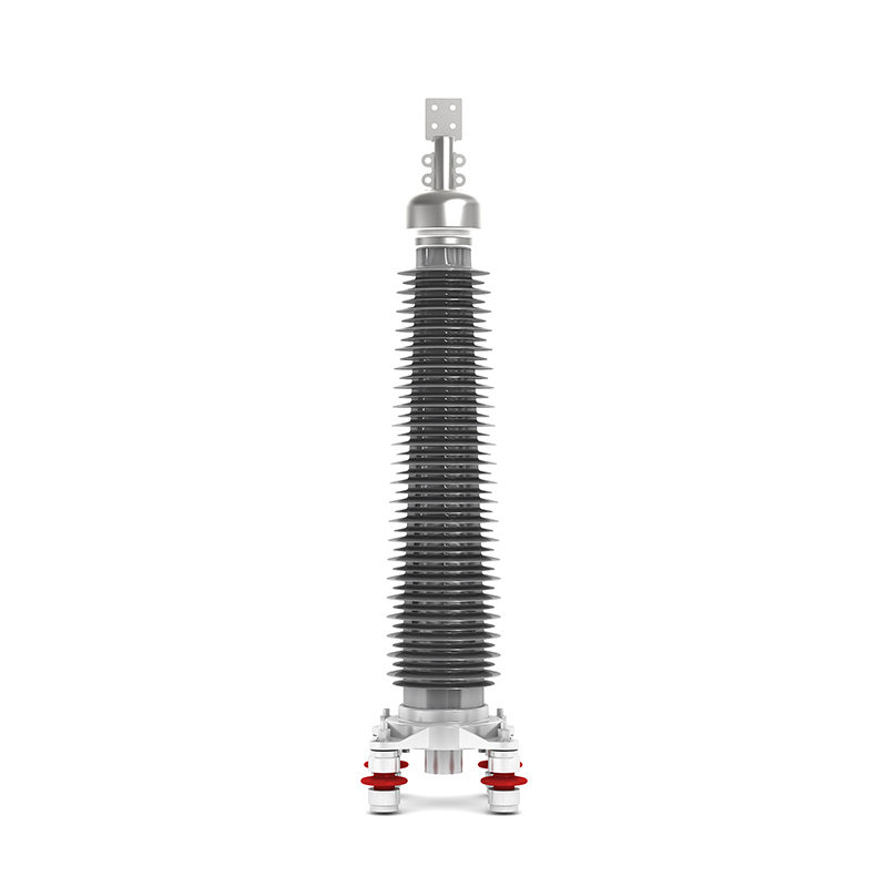
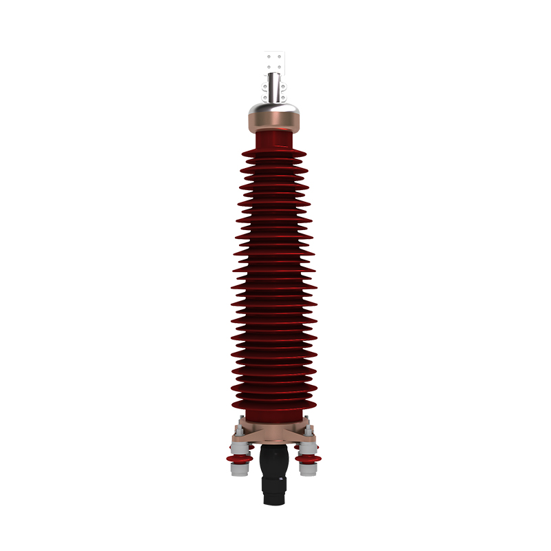
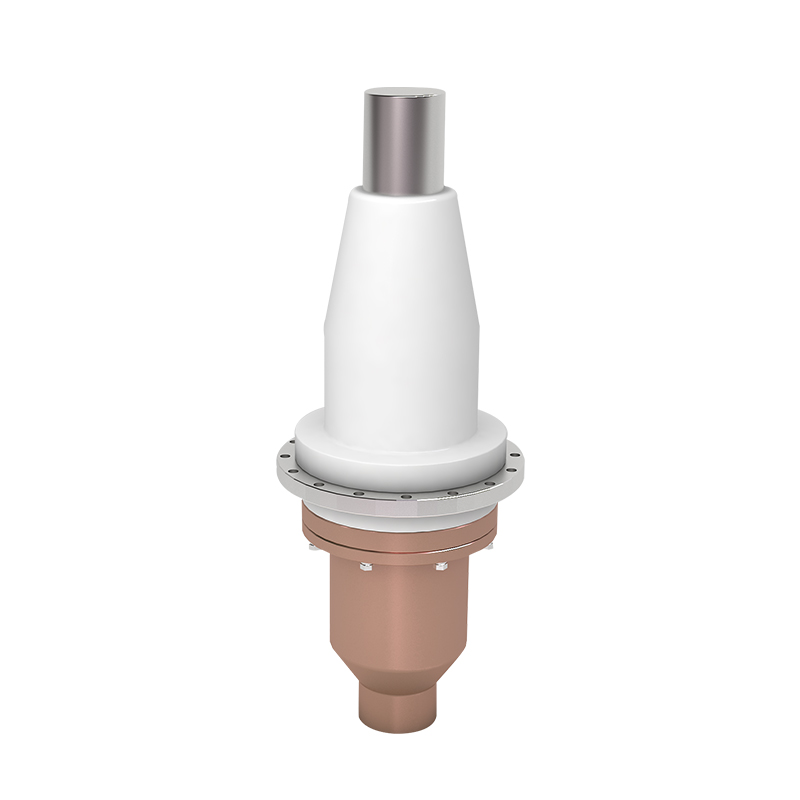
Recommended Products
The variety of models, to meet the development needs of various regions in the world.
Copyright © Shanghai Yongjin Electric Technology Co.,Ltd.

China Power Quality Solutions Supplier