 English
 中文简体
中文简体 русский
 Español
 عربى
عربى
Industry News
How Does DC Link Capacitor Improve Stability In Electrical Circuits
What Electrical Role Does a DC Link Capacitor Perform Inside Circuit Architecture
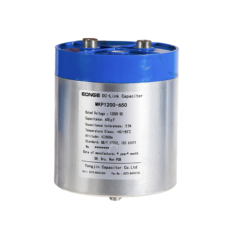
DC Link Capacitor usually sits between two working stages inside a power circuit. One side receives converted electricity, the other side sends it toward load equipment. In between, voltage does not stay perfectly steady. Small shifts appear during switching, and the capacitor sits right in that middle path to handle those changes.
In many real systems, power flow moves in pulses instead of a smooth line. Rectifier action, inverter switching, and load variation all create uneven movement on the DC bus. Capacitor takes part of that fluctuation into its internal structure, holding energy for a short moment and releasing it when the circuit needs support again.
Work with Capacitor Supplier often begins at design stage, where circuit conditions decide how the component will be shaped and arranged. Different electrical environments place different pressure on the DC link section, so matching structure with working behavior becomes part of early planning rather than later adjustment.
How Does a DC Link Capacitor Smooth Voltage Ripple in Power Conversion
Voltage ripple appears naturally when alternating current is converted into direct current or when DC is switched back into AC. Instead of a flat line, voltage moves slightly up and down during each conversion cycle.
DC Link Capacitor reacts to that movement in a repeating pattern. When voltage rises, energy moves into the capacitor. When voltage drops, stored energy moves back into the circuit. This back-and-forth behavior reduces visible fluctuation on the DC bus.
The process does not stop between cycles. It keeps repeating in small steps, following switching rhythm of the system. Downstream components receive a more stable supply pattern because those small ripples are absorbed before reaching sensitive areas.
In practical operation, smoothing is not a single event. It behaves more like continuous balancing where capacitor adjusts charge level depending on instant circuit condition.
How Does Energy Buffering Work in a DC Link Capacitor
Energy buffering inside DC Link Capacitor happens when circuit demand changes faster than power source response. Load may suddenly draw more current, while source output stays momentarily unchanged. That gap creates short voltage dips in many systems.
Capacitor reduces that gap by releasing stored energy into the DC link. The release is quick, almost immediate, filling the space between demand and supply. After that moment, capacitor returns to charging state again when circuit stabilizes.
This cycle repeats often during normal operation. It does not require external control once installed inside the circuit path.
Buffering behavior can be described in simple steps:
- Load demand increases suddenly
- Voltage begins to drop
- Capacitor releases stored charge
- Circuit voltage stabilizes again
- Capacitor returns to charge state
Energy buffering does not increase total system power, yet it changes how energy is delivered over time, making circuit behavior feel more even during load shifts.
How Does a Capacitor Handle Surge and Transient Events
Surge events appear when electrical conditions change too quickly for normal flow to adjust. Switching actions, load disconnection, or sudden reconnection can create short voltage spikes inside the circuit.
Capacitor absorbs part of that spike energy. Instead of letting it pass directly into sensitive components, the capacitor temporarily stores it within internal structure. After the surge passes, energy is released back in a controlled way.
This reaction helps reduce stress on switching devices that sit downstream in the circuit path. Without this buffer, those components may face sharp voltage peaks during operation.
Typical transient handling process:
- Sudden voltage rise appears on DC line
- Capacitor receives excess energy
- Internal charge distribution adjusts
- Energy returns gradually into circuit flow
Surge handling happens many times during normal operation, especially in systems where switching frequency changes often.
How Does a Capacitor Reduce Electrical Noise and EMI
Electrical noise appears when fast switching creates high-frequency disturbance inside power circuits. These small signals travel through conductors and may interfere with stable operation of nearby components.
DC Link Capacitor helps reduce that effect by giving high-frequency energy an easier path to follow. Instead of moving further into sensitive areas, noise energy is absorbed or redirected within capacitor and surrounding grounding paths.
Low-frequency power continues through normal route, while high-frequency disturbance gets reduced at the DC link stage. This separation helps keep signal behavior more stable across the system.
Noise reduction actions include:
- Absorbing high-frequency ripple from switching stages
- Reducing harmonic distortion in DC bus
- Limiting signal interference between circuit sections
- Stabilizing reference voltage for connected loads
In practical systems, noise control is not handled by one part alone. Capacitor works together with layout design and grounding paths to keep overall electrical behavior balanced.
How Do Different Capacitor Structures Affect DC Link Behavior
Different internal structures of DC Link Capacitor change how it responds inside a circuit. Film type and electrolytic type show different behavior patterns depending on how energy is stored and released.
Film-based structure responds quickly to voltage changes. It handles ripple movement with fast reaction, which supports smoother waveform behavior in switching environments.
Electrolytic-based structure focuses more on energy storage. It holds larger charge capacity, supporting longer buffering during load variation. Response speed is slower compared with film type, yet energy support is stronger.
Hybrid structure combines both behaviors in a balanced way, supporting ripple control and buffering together inside one design.
Selection depends on switching pattern, load change speed, and stability requirement inside the circuit path.
| Structure Type | Response Character | Energy Behavior | Typical Circuit Role |
|---|---|---|---|
| Film-based | Fast adjustment to change | Moderate storage | Ripple smoothing stage |
| Electrolytic-based | Slower response | Higher energy holding | Load buffering stage |
| Hybrid design | Balanced reaction | Mixed behavior | Combined DC link support |
How Does Internal Material Structure Influence Capacitor Stability
Inside a DC Link Capacitor, structure is not only a design detail. It decides how charge moves, settles, and returns during every switching cycle. Layers inside the component sit very close to each other, separated by dielectric material that reacts each time voltage changes on the DC bus.
When switching action repeats, internal charge does not stay still. It shifts back and forth in small steps. Some internal materials settle quickly after each change, while others hold residual energy a bit longer before returning to balance. That difference shows up as stability or small drift in circuit behavior.
Heat builds during operation, especially in systems where switching happens often. Temperature rise affects how easily charge moves through internal paths. A structure that tolerates that movement without large variation tends to keep DC link behavior calmer over time.
Material aging does not appear suddenly. It develops through repeated electrical stress, where each cycle adds a small change. Over long use, those small changes begin to show as slower response or uneven smoothing.
Between rectifier and inverter, DC Link Capacitor sits in a position where energy direction keeps changing. Rectifier side sends converted energy into the DC rail, while inverter side pulls energy out in a controlled switching pattern.
Without a buffer, both sides would interact directly, passing every fluctuation forward. Capacitor breaks that direct transfer. Energy enters, gets stored for a short moment, then leaves in a more controlled form.
When rectifier output rises unevenly, capacitor takes in extra charge instead of letting voltage spike travel further. When inverter demand increases suddenly, capacitor fills the gap before upstream source adjusts.
The behavior feels like a small waiting space in the middle of two fast-moving processes. Not blocking energy, not forcing it forward, just adjusting timing so both sides do not disturb each other too sharply.
What Problems Appear When Capacitor Response Weakens
A weakening capacitor does not fail in a single step. Changes usually appear in layers, starting from small irregularities in voltage behavior. Ripple that used to stay contained may begin to show up more clearly on the DC bus.
Load changes also feel less smooth. When demand rises, voltage dip becomes more visible, and recovery takes a slightly longer path back to stable level. That delay often points to reduced buffering ability inside the capacitor.
Heat around switching devices can also increase. When capacitor stops absorbing enough energy, surrounding components take on more stress. Over time, thermal balance inside the circuit shifts away from normal pattern.
Noise levels may rise as well. High-frequency disturbance that used to be absorbed starts traveling further along circuit paths, affecting nearby sections.
Typical signals of weakened behavior include:
- Ripple becoming more noticeable during operation
- Slower recovery after load change
- Extra heat near switching area
- More electrical noise in signal paths
- Uneven voltage feel during fast transitions
None of these appear suddenly in most cases. They build slowly through repeated operation cycles.
How Do DC Link Capacitor Supplier Influence System Behavior
Selection of DC Link Capacitor often depends on how consistent internal construction remains across supply batches. Capacitor Supplier is not only delivering a part, but also defining how that part behaves under real circuit stress.
Small changes in internal layering, material thickness, or sealing method can shift how capacitor reacts under ripple or transient conditions. Even when external size looks identical, internal response may differ slightly between sources.
Designers usually match supplier behavior with circuit rhythm. Fast switching systems need components that react quickly to voltage changes. Systems with slower load variation can tolerate different energy movement patterns.
Important points linked to supplier variation:
- Consistency of internal structure from batch to batch
- Stability under repeated heating cycles
- Response speed under switching stress
- Level of ripple absorption under load changes
- Long-term drift in electrical behavior
| Focus Area | Circuit Expectation | Supplier Behavior Factor |
|---|---|---|
| Ripple control | Smooth DC bus | Fast charge response |
| Load support | Stable voltage during change | Strong energy release |
| Heat tolerance | Reduced thermal drift | Stable internal material |
| Long use behavior | Low variation over time | Consistent internal build |
How Does DC Link Capacitor Behavior Shift in Modern Electrical Systems
Modern power circuits tend to switch faster and operate in tighter spaces. That combination changes how DC Link Capacitor is stressed during normal use. Instead of long steady cycles, operation now includes frequent short transitions where voltage rises and falls in quick succession.
In that condition, capacitor works almost continuously, adjusting charge levels in small steps rather than long storage cycles. Reaction speed becomes more noticeable, since there is less idle time between changes.
Physical layout also plays a role. Components sit closer together, which increases interaction between heat, noise, and switching behavior. Capacitor response becomes part of a wider system effect rather than an isolated function.
Load behavior has also become less constant. Changes happen more often, which places repeated demand on buffering and ripple control at the same time.
What Practical Adjustments Improve Capacitor Stability in Circuits
Stability in real circuits is not only about choosing a capacitor, but also about how it is placed and supported inside the system. Electrical paths around it influence how fast it can respond to changes in voltage.
Short connections help reduce delay between charge movement and circuit demand. When electrical path is long or indirect, response becomes slower and ripple may pass further before being corrected.
Thermal balance also matters. When heat accumulates in one area, capacitor behavior can drift slightly. Spreading components and avoiding tight clustering helps keep temperature more even during operation.
In some circuit designs, more than one capacitor is used in parallel. That approach spreads load and reduces pressure on a single unit, making overall response more stable during repeated switching cycles.
Common layout practices include:
- Keeping electrical paths short and direct
- Placing capacitor close to switching stages
- Distributing heat across the circuit area
- Using multiple capacitors for shared load
- Maintaining stable grounding paths for noise control
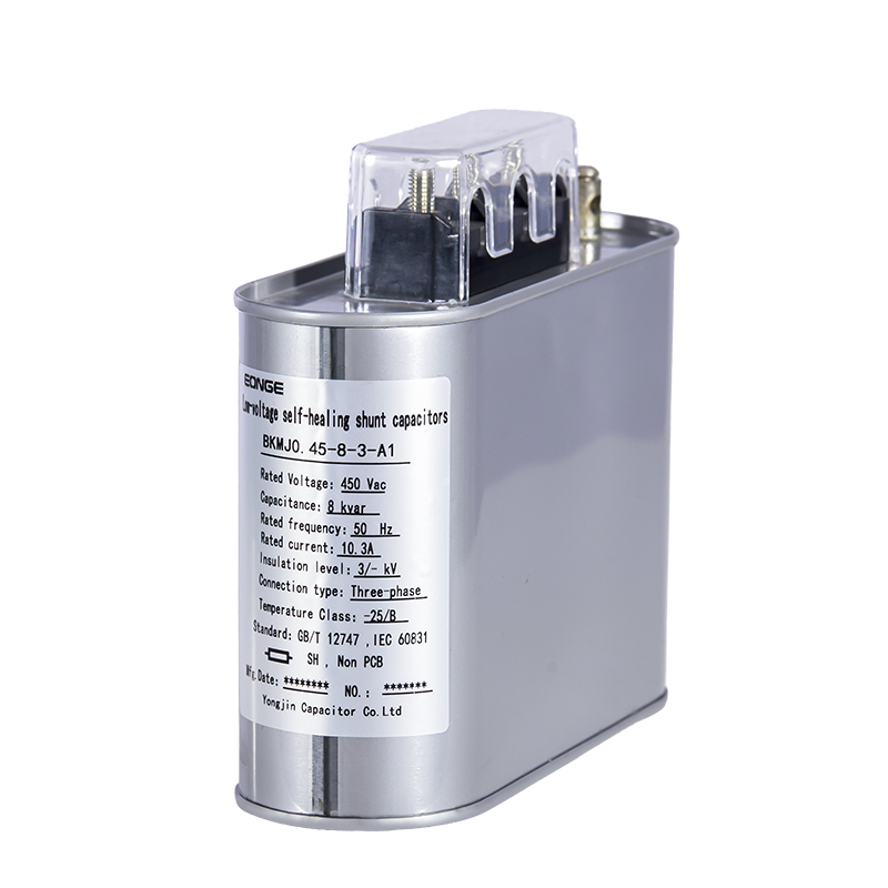
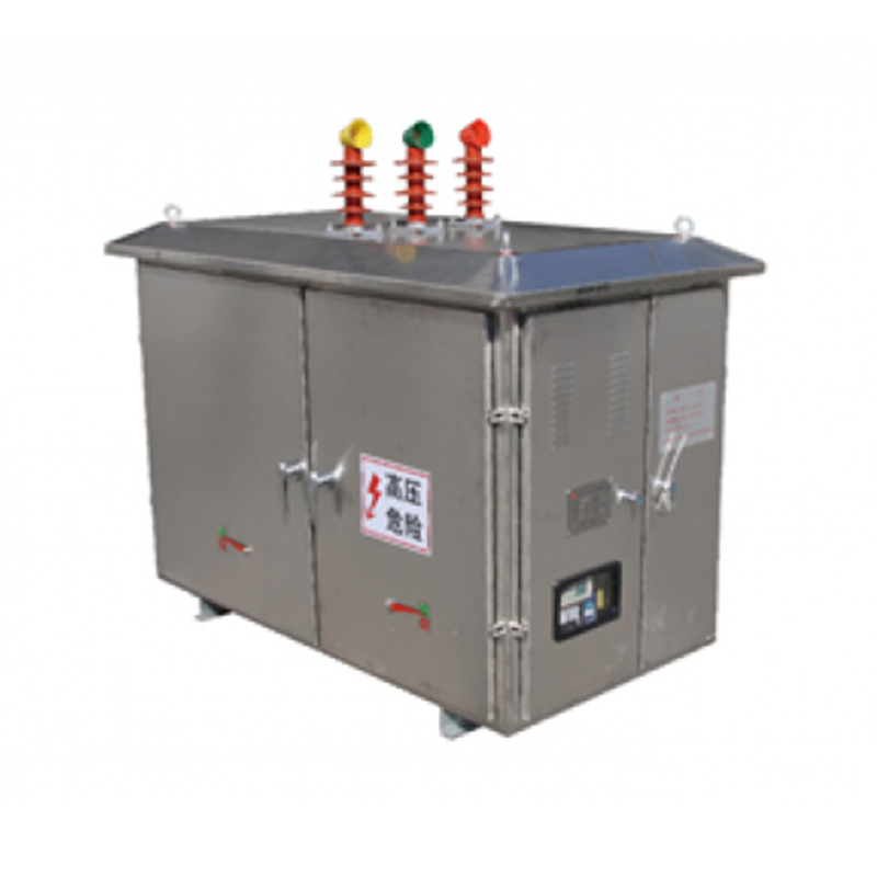
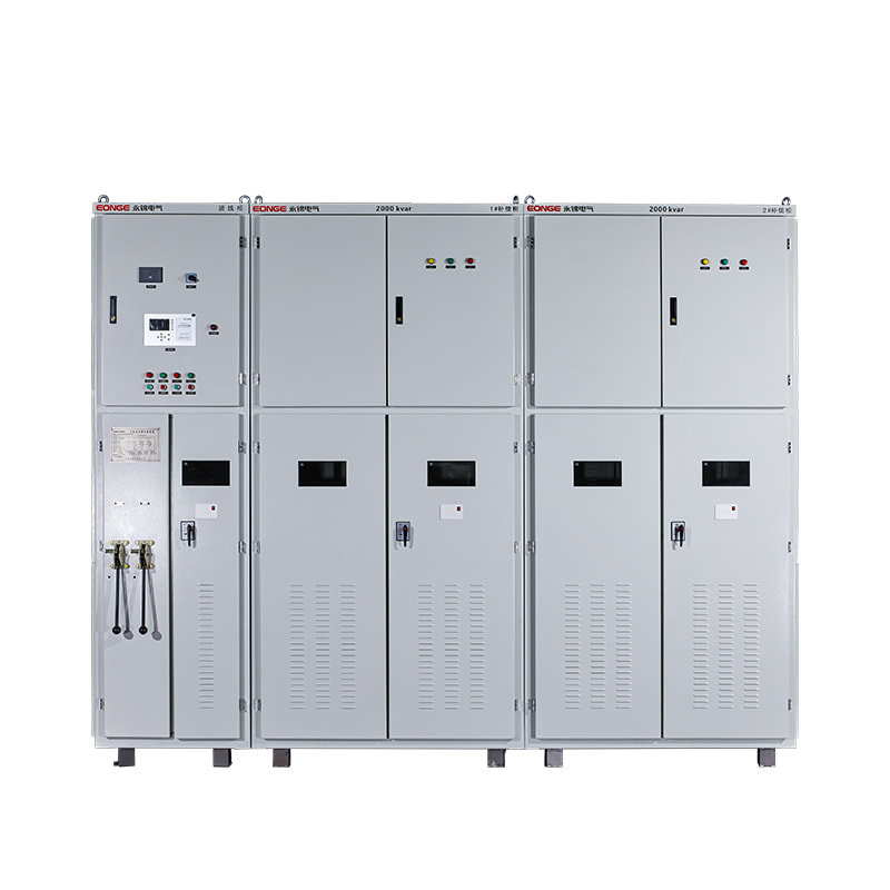
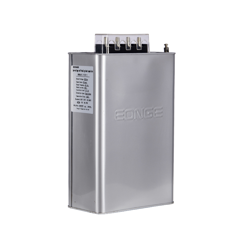
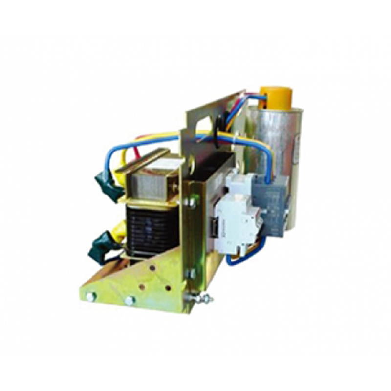
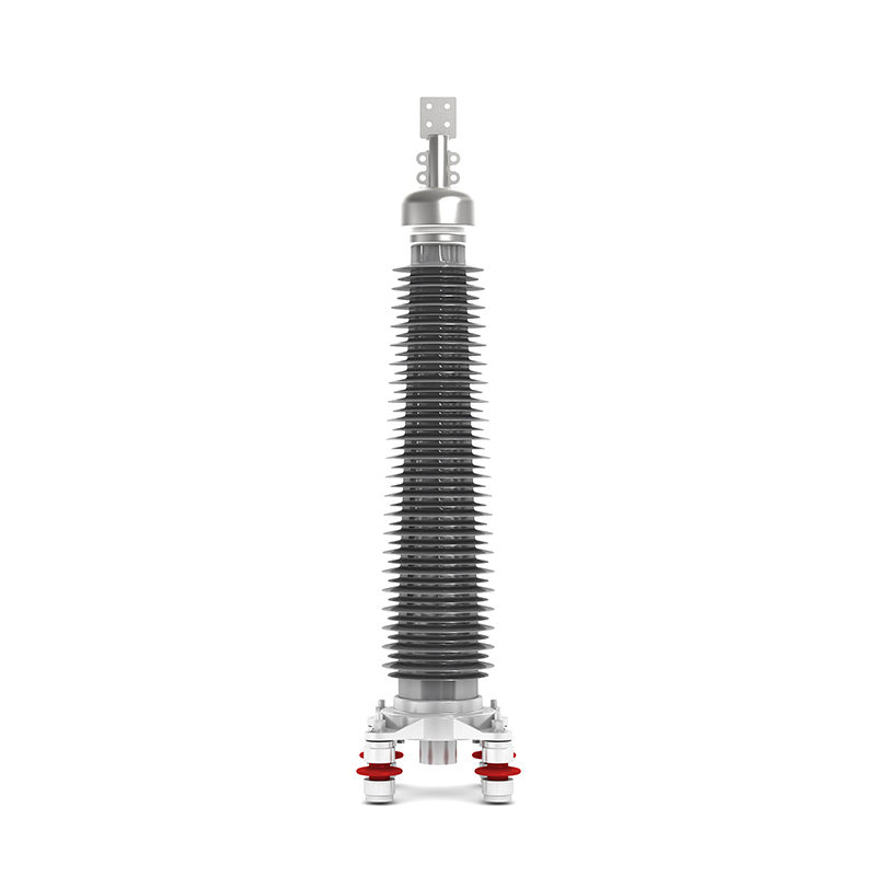
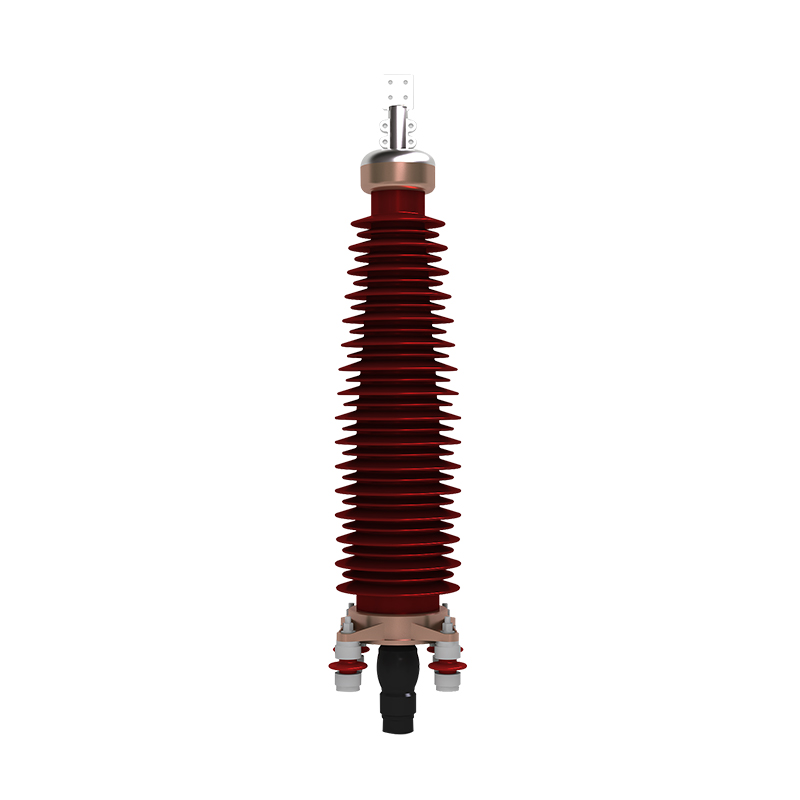
Recommended Products
The variety of models, to meet the development needs of various regions in the world.
Copyright © Shanghai Yongjin Electric Technology Co.,Ltd.

China Power Quality Solutions Supplier