 English
 中文简体
中文简体 русский
 Español
 عربى
عربى
Industry News
Why Is DC Link Capacitor Important In Power Conversion Systems
A power conversion system takes electricity in one form and changes it to another. Many systems first convert alternating current to direct current. That direct current then gets converted back to alternating current at a different voltage or frequency. Between these two stages sits a key component.
That component is the DC Link Capacitor. It connects the rectifier output to the inverter input. The rectifier produces direct current with some leftover ripple. The inverter expects a steady direct voltage. The DC Link Capacitor smooths out the difference between what the rectifier delivers and what the inverter needs.
| Function | What the Capacitor Does | Why It Matters |
|---|---|---|
| Voltage Smoothing | Fills gaps between rectifier pulses | Provides steady DC to the inverter |
| Energy Storage | Holds charge for short term demands | Supplies power during load changes |
| Ripple Absorption | Shunts AC components to ground | Reduces stress on switching devices |
| Decoupling | Separates rectifier and inverter actions | Prevents interaction between stages |
| Transient Support | Delivers current during voltage dips | Keeps the system running through short disturbances |
The DC Link Capacitor also provides a low impedance path for high frequency currents. The inverter switches on and off at high speed. Each switching event creates a current demand. The capacitor supplies that demand from its stored energy. Without the capacitor, the current would have to travel back through the rectifier and the input supply. That path has higher impedance. The voltage would drop during each switching cycle.
Where Is the DC Link Capacitor Located Between Power Stages
The physical placement of the DC Link Capacitor follows the electrical path. On one side, wires or bus bars connect to the rectifier output. On the other side, connections run to the inverter input. The capacitor sits as close as possible to the inverter switching devices. Short connections keep the loop inductance low.
Low inductance matters because high frequency currents need a quick path. A long wire acts like an antenna. It radiates noise. It also creates voltage spikes when current changes rapidly. Placing the capacitor close to the inverter minimizes these problems.
The capacitor connects across the positive and negative DC bus rails. One terminal goes to the positive rail. The other goes to the negative rail. The capacitor sees the full DC bus voltage across its terminals. The voltage rating of the capacitor must exceed the expected bus voltage.
In a three phase system, the Capacitor connects after the three phase rectifier. The rectifier produces a six pulse DC waveform. The capacitor smooths the six pulses into a nearly flat line. The remaining ripple has a frequency six times the input line frequency.
In a single phase system, the rectifier produces a two pulse waveform. The gaps between pulses are larger. The Capacitor needs more capacitance to fill those longer gaps. Single phase systems often use larger capacitors than three phase systems for the same power level.
How Does the Capacitor Smooth Voltage After Rectification
The rectifier does not produce perfect DC. It produces pulses of current. Between pulses, the voltage would fall to zero without a capacitor. The DC Link Capacitor charges during each pulse. Between pulses, the capacitor discharges into the load.
The charging and discharging happen continuously. The capacitor voltage rises slightly during the charge phase. The voltage drops slightly during the discharge phase. The difference between the highest and lowest voltage is the ripple voltage. A larger capacitor produces smaller ripple.
The capacitor acts like a reservoir. The rectifier fills the reservoir. The load draws from the reservoir. As long as the rectifier fills the reservoir faster than the load empties it, the voltage stays within an acceptable range. When the load draws more current, the voltage drops more between pulses. The capacitor must be sized for the maximum expected load current.
The smoothing action also depends on the capacitor's equivalent series resistance. Every capacitor has some internal resistance. Current flowing through that resistance creates heat. The heat raises the capacitor temperature. High internal resistance reduces the smoothing effectiveness because some of the stored energy turns into heat instead of supporting the load.
Manufacturers of components like Shanghai Yongjin Electric Technology Co., Ltd. focus on producing capacitors with controlled internal resistance. The goal is to keep energy losses low while maintaining reliable operation across different load conditions. The balance between capacitance value, voltage rating, and internal resistance determines how well a DC Link Capacitor performs its smoothing function.
What Happens to the System Without a Proper Capacitor
A power conversion system missing its Capacitor does not work correctly. The inverter sees the raw rectifier output. That output contains large voltage drops between pulses. The inverter tries to switch during those drops. The output waveform becomes distorted.
The voltage drops also affect the inverter switching devices. A switching device needs a minimum voltage to turn on properly. When the DC bus voltage falls below that level, the device operates in an inefficient region. It generates more heat. The heat damages the device over time.
The current drawn from the rectifier becomes peaky. Without the capacitor, the rectifier must supply all the current during the pulses. The peak current is much higher than the average current. The rectifier diodes or thyristors experience higher stress. The input wiring and fuses must handle higher peak currents.
The system also becomes sensitive to load changes. When the load demands more power, the voltage drops immediately. The inverter tries to compensate by drawing more current. The voltage drops further. The system may enter a unstable state where voltage and current oscillate.
Electromagnetic interference increases without the DC Link Capacitor. The high frequency switching currents have no local source. They travel back through the rectifier and into the input wiring. Those wires radiate noise. Nearby equipment may experience malfunctions from the radiated emissions.
How Does the Capacitor Supply Peak Current During Motor Startup
A motor starting from rest draws a large current. The current can be several times higher than the motor's rated running current. That starting current comes from the DC Link Capacitor. The capacitor discharges into the inverter, which delivers the current to the motor.
The rectifier cannot respond immediately to the sudden current demand. The rectifier has its own internal impedance and possibly input inductors that limit how fast current can increase. The capacitor fills the gap between the demand and what the rectifier can supply.
As the motor accelerates, the current demand decreases. The rectifier catches up and recharges the capacitor. The capacitor voltage returns to its normal level. The process repeats each time the motor starts.
The capacitor must withstand the high discharge current during motor starting. The internal connections and the terminals must carry the peak current without overheating. The capacitor's ripple current rating matters for motor start applications. Repeated starts cause repeated heating cycles.
A system that starts a motor many times per hour needs a Capacitor designed for frequent high current pulses. A system that starts a motor once per day has different requirements. The capacitor supplier provides guidance on selecting the right part for the duty cycle.
The starting current also creates a voltage drop across the capacitor's internal resistance. That voltage drop subtracts from the available bus voltage. A capacitor with low internal resistance delivers more voltage to the inverter during motor starting. The motor receives higher voltage and starts more quickly.
Why Do Regenerative Energy Flows Rely on the Capacitor
When a motor slows down, it acts as a generator. The motor returns energy back toward the power source. That returning energy flows into the DC link. The DC Link Capacitor must absorb that energy without allowing the voltage to rise too high.
The capacitor stores the regenerative energy temporarily. The voltage across the capacitor increases as energy flows in. If the voltage rises too much, the inverter or the capacitor may be damaged. A braking circuit or a regenerative power supply normally handles the excess energy. But even with those systems, the capacitor must absorb the initial surge.
The capacitor also provides a place for the regenerative current to go during the time between when the energy arrives and when the braking circuit activates. That time period is very short, measured in microseconds. A capacitor that cannot handle high peak currents may fail during regenerative events.
The regenerative current flows in the opposite direction from normal power flow. The capacitor does not care about direction. It absorbs current in either direction. That bidirectional capability makes the DC Link Capacitor well suited for systems where motors start and stop frequently.
In systems without regenerative braking, the excess energy still needs somewhere to go. The capacitor absorbs the energy and the voltage rises. A voltage monitoring circuit detects the rise and activates a braking resistor. The resistor dissipates the energy as heat. The capacitor's voltage returns to normal.
The size of the Capacitor affects how much regenerative energy the system can absorb without a braking circuit. A larger capacitor stores more energy. The voltage rises less for the same amount of returned energy. The system can handle more regenerative events before needing to activate the braking resistor.
How Does a Solar Inverter Use the Capacitor
A solar panel produces direct current that varies with sunlight. Clouds pass overhead. The sun moves across the sky. A solar inverter must convert that variable DC into stable AC for the grid or for local loads. The DC Link Capacitor helps manage the variability.
The capacitor sits between the solar panel input and the inverter stage. When the sun is bright, the solar panel produces more current. The capacitor charges to a higher voltage. When a cloud passes, the panel current drops. The capacitor discharges to maintain the inverter input voltage.
The solar inverter also performs a function called maximum power point tracking. The inverter adjusts its input current to find the voltage where the solar panel produces the most power. The Capacitor allows this adjustment to happen smoothly. Without the capacitor, the voltage would jump around as the inverter changed its current draw.
The capacitor also filters out high frequency noise from the inverter switching. Solar panels have large surface areas. That area can act as an antenna. Without proper filtering, the inverter switching noise would radiate from the solar panels. The Capacitor provides a low impedance path for that noise.
What Happens to Variable Solar Output Before Entering the Grid
The inverter must match the grid voltage and frequency exactly. Any variation on the DC side causes problems on the AC side. The DC Link Capacitor reduces those variations before they reach the inverter stage.
The capacitor's stored energy acts as a buffer. When the solar output increases, the capacitor absorbs the extra energy. The inverter sees a steady voltage. When the solar output decreases, the capacitor releases stored energy. The inverter continues to see a steady voltage.
The capacitor also helps the inverter ride through short interruptions. A bird flies over a solar panel. The shadow reduces output for a second. The capacitor supplies energy during that second. The inverter keeps running. The grid sees no disturbance.
The size of the capacitor for a solar inverter depends on the panel area and the expected rate of change of sunlight. A large solar farm needs a different capacitor than a small residential system. The inverter manufacturer selects the capacitor based on the system's response time requirements.
What Signs Indicate a Drying Out Electrolytic Capacitor
An electrolytic DC Link Capacitor contains liquid electrolyte. Over time, the electrolyte can evaporate. The capacitor loses capacitance. The equivalent series resistance increases. The capacitor no longer performs its smoothing function properly.
One sign of a drying capacitor is increased voltage ripple. The DC bus voltage shows more variation than normal. The ripple frequency may be the same as before, but the amplitude is larger. A technician measuring the DC bus with an oscilloscope sees the increased ripple.
Another sign is increased operating temperature. A drying capacitor has higher internal resistance. The resistance creates heat when current flows. The capacitor runs hotter than before. The increased heat accelerates the drying process. The capacitor enters a cycle of increasing temperature and decreasing performance.
The system may also show intermittent faults. The DC bus voltage dips during load changes. The inverter may trip on undervoltage protection. The system resets and works normally for a while. The fault happens again under similar conditions.
The smell of the capacitor can also change. A drying capacitor may emit a fishy or chemical smell. The smell comes from the electrolyte breaking down. A strong smell indicates advanced drying.
Capacitor suppliers provide expected lifetime ratings for their products. Those ratings assume certain operating temperatures. A capacitor running at a higher temperature than specified will dry out faster. Proper cooling extends the working life.
How Does a Failed Capacitor Shut Down the Whole Conversion System
A failed DC Link Capacitor takes the entire power conversion system offline. The failure mode depends on the capacitor type. An electrolytic capacitor may short circuit. A film capacitor may open circuit. Either failure stops normal operation.
A short circuit across the DC bus creates a direct path from positive to negative. The rectifier tries to supply unlimited current into the short. Fuses blow or circuit breakers trip. The system shuts down completely. The short may also damage the rectifier diodes or the inverter switching devices before the protection activates.
An open circuit failure removes the capacitor from the system. The DC bus voltage becomes unstable. The inverter sees the raw rectifier output. The ripple voltage is too high for proper switching. The inverter shuts down on overvoltage or undervoltage protection.
In some cases, a failed capacitor takes other components with it. A shorted capacitor dumps all its stored energy into the short. That energy can vaporize copper traces on a circuit board. The arc from a sudden short can damage nearby components.
The system may also fail gradually. The capacitor loses capacitance over time. The ripple voltage increases. The inverter switching devices experience higher stress. One device eventually fails. The system stops working. The root cause was the aging capacitor, but the visible failure was the switching device.
Regular maintenance includes checking DC Link Capacitors. A technician measures capacitance and equivalent series resistance. Any significant change from the original values indicates a problem. Replacing capacitors before they fail prevents unexpected system shutdowns.
What Testing Methods Verify Capacitor Reliability Before Shipping
A DC Link Capacitor Supplier tests every component before shipping. The tests verify that the capacitor meets its specifications. The tests also catch manufacturing defects that could cause early failure.
The capacitance test measures the actual capacitance value. A meter applies a small AC voltage and measures the resulting current. The calculated capacitance must fall within the specified tolerance range. A capacitor outside the range gets rejected.
The equivalent series resistance test measures the internal resistance. A low resistance is good. A high resistance indicates poor internal connections or damaged electrolyte. The test uses a high frequency signal to separate the resistance from the capacitance.
The insulation resistance test checks the dielectric between the electrodes. A high voltage is applied across the capacitor terminals. The leakage current is measured. Low leakage current indicates good insulation. High leakage current suggests a weak spot in the dielectric.
The voltage withstand test applies a voltage higher than the rated voltage for a short time. The capacitor must survive without breaking down. The test proves that the capacitor has margin above its normal operating voltage.
Temperature cycling tests expose capacitors to alternating hot and cold conditions. The thermal expansion and contraction stress the internal connections. A capacitor with weak connections will fail during temperature cycling. A good capacitor survives the cycling without changing its electrical properties.
The supplier provides test reports to customers. The reports show the test results for each batch of capacitors. A customer can verify that the capacitors meet the required specifications before installing them in a power conversion system.
Why Do Higher Switching Frequencies Demand Better Capacitor Performance
Modern power conversion systems use higher switching frequencies than older designs. Higher frequencies allow smaller transformers and inductors. The whole system becomes smaller and lighter. But higher frequencies put more stress on the DC Link Capacitor.
The capacitor must absorb ripple current at the switching frequency. A higher switching frequency means more ripple current cycles per second. The capacitor heats up more from the same amount of ripple current. The capacitor needs lower internal resistance to keep the temperature acceptable.
The self heating from ripple current matters more at higher frequencies. The capacitor's internal resistance changes with frequency. Some capacitors have higher resistance at high frequencies. Those capacitors are not suitable for high switching frequency systems.
The inductance of the capacitor also matters. Every capacitor has some internal inductance. At high frequencies, that inductance becomes significant. The capacitor may not respond quickly enough to current demands. The voltage dips between the capacitor and the switching devices.
Capacitor suppliers have responded to higher switching frequencies by developing new products. Film capacitors with low inductance construction are common. Electrolytic capacitors with improved high frequency performance are also available. The right capacitor for a high frequency system looks different from a capacitor for a low frequency system.
The trend toward higher switching frequencies continues. New semiconductor materials switch faster than older silicon devices. The DC Link Capacitor must keep pace. A capacitor that worked well in a previous generation system may not work in a new high frequency design.

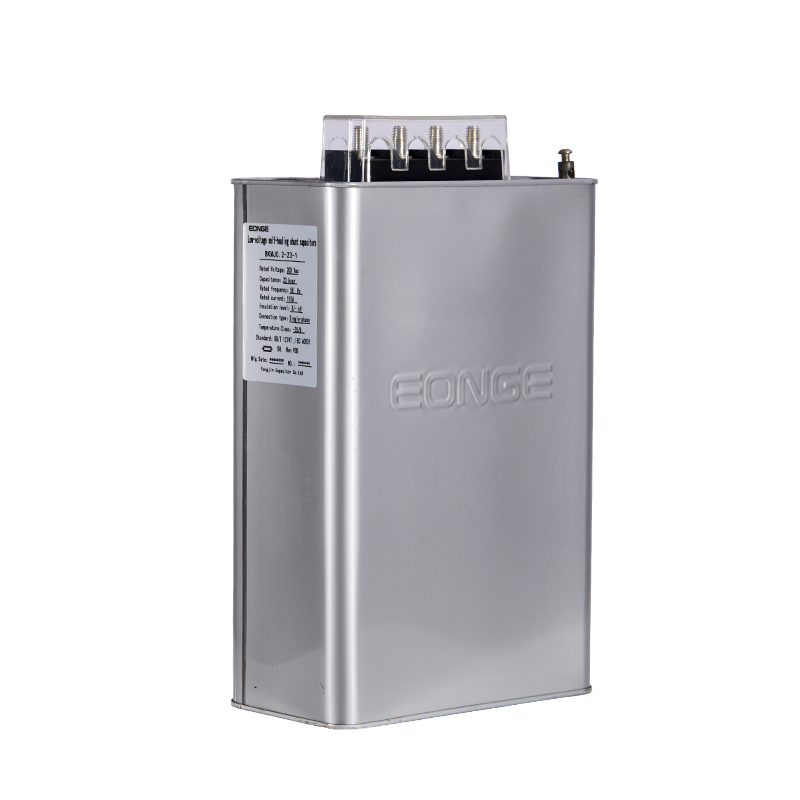
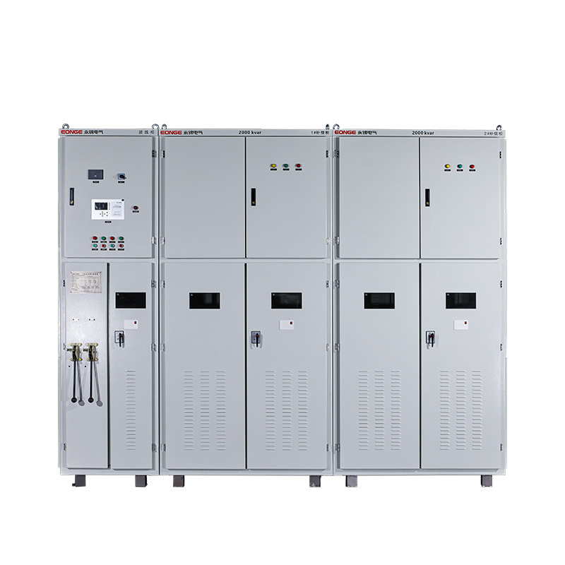

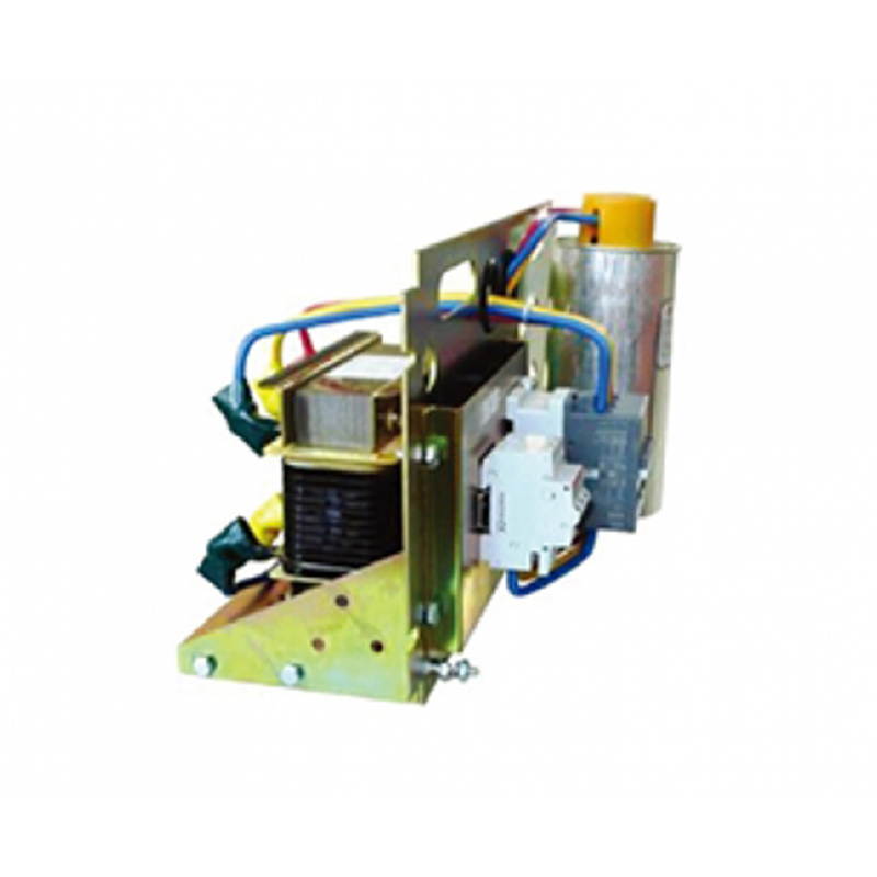
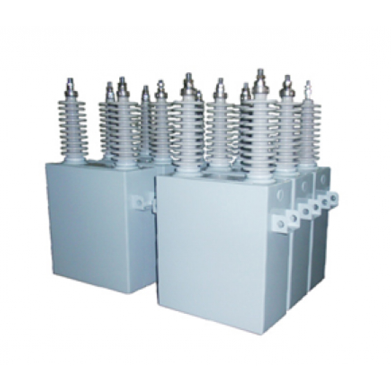
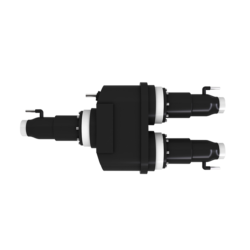
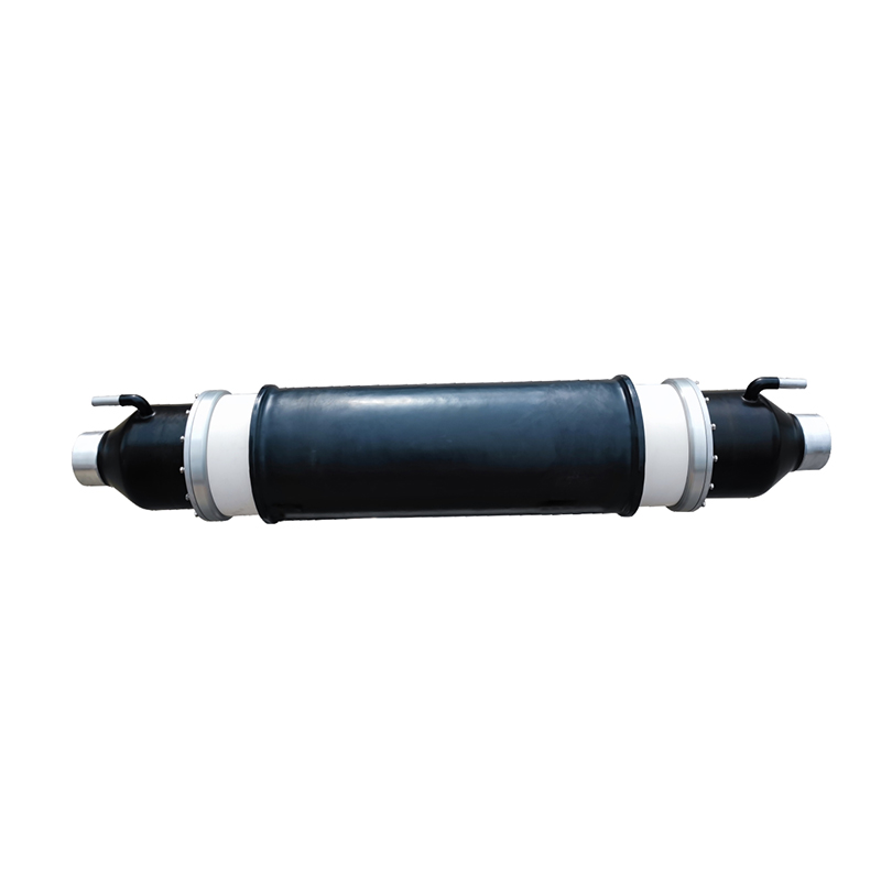
Recommended Products
The variety of models, to meet the development needs of various regions in the world.
Copyright © Shanghai Yongjin Electric Technology Co.,Ltd.

China Power Quality Solutions Supplier