 English
 中文简体
中文简体 русский
 Español
 عربى
عربى
Industry News
What Problems Occur When Low Voltage Capacitor Is Used Incorrectly
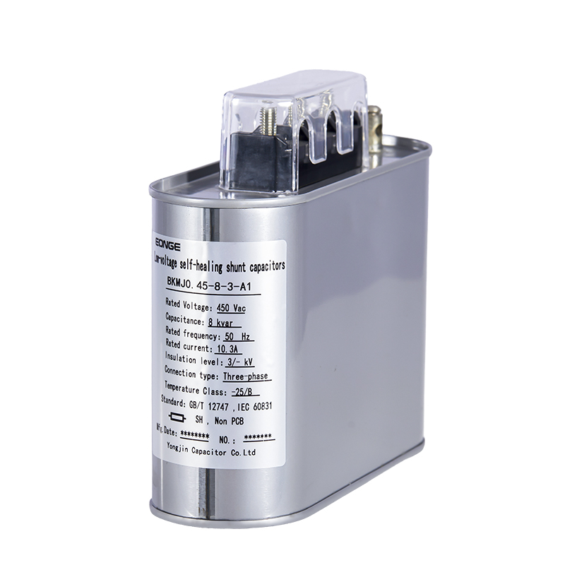
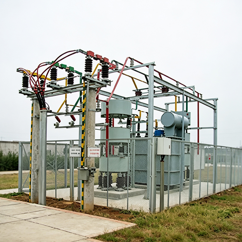
Low voltage capacitor often appears inside familiar power environments such as workshop distribution boxes, building electrical panels, and small industrial lines, where the main purpose stays connected with balancing reactive power and keeping voltage behavior relatively steady during changing loads.
In real operation, electrical demand rarely stays constant. Machines start and stop, lighting loads switch in cycles, and small devices draw uneven current patterns across time. Low voltage capacitor responds directly to those variations, meaning performance depends heavily on whether operating conditions stay close to the intended range or drift into unfamiliar load behavior.
Once application boundaries are ignored, capacitor interaction with the system no longer follows smooth compensation behavior. Electrical response begins to reflect surrounding instability, and that instability gradually shows up as heat changes, current imbalance, or irregular voltage movement across connected circuits.
How low voltage capacitor behaves inside a working circuit
Inside alternating current systems, low voltage capacitor works through repeated energy exchange with the electrical waveform. Energy is stored during one phase of the cycle and released during another phase, helping reduce unnecessary reactive current and supporting smoother voltage behavior.
In practical environments such as workshop machinery or building distribution panels, this process is not isolated. Multiple devices switch at different times, so current waveforms overlap and reshape continuously. Capacitor response adjusts in real time, following these changes rather than operating in a fixed pattern.
A stable environment allows this exchange to remain balanced. Load variation within expected range creates predictable charging and discharging cycles. Electrical stress remains distributed across internal components instead of concentrating in specific zones.
What happens when load conditions do not match capacitor usage
Incorrect usage often starts from mismatch between system demand and capacitor capacity. In practical settings, this can happen when additional equipment is added to a workshop line or when lighting load expands inside a building without recalculating compensation needs.
When mismatch occurs, current flow inside the circuit no longer distributes evenly. Certain branches carry more reactive demand, while capacitor response continues based on original configuration. That difference creates uneven compensation behavior across the system.
Typical field observations include:
- voltage fluctuation in specific circuit sections
- uneven current flow between parallel branches
- repeated switching of compensation units
- noticeable heating around connection points
| Operating Condition | Electrical Behavior | Practical Effect |
|---|---|---|
| Balanced load | Stable compensation flow | Smooth circuit behavior |
| Partial mismatch | Uneven current sharing | Local voltage variation |
| Strong mismatch | Irregular compensation cycle | Frequent system adjustment |
In daily environments such as small factories or commercial buildings, these patterns often appear gradually rather than immediately, which makes early detection dependent on routine observation of electrical behavior.
How thermal behavior changes under incorrect application
Low voltage capacitor generates heat during operation as part of normal energy exchange, especially when current flow increases or waveform becomes irregular due to surrounding load conditions.
In practical installations, heat does not distribute evenly inside the unit. Internal dielectric layers respond differently depending on temperature exposure, and over time, uneven thermal zones begin to form inside the structure.
Real-world influence factors include:
- limited ventilation inside electrical cabinets
- nearby heat sources from other equipment
- continuous switching cycles during peak load periods
- accumulation of heat during long operating hours
When heat removal is slow, internal temperature rises gradually. Expansion and contraction inside materials repeat with each cycle, creating slow mechanical stress that influences internal stability over time.
Even in common environments such as machine rooms or building basements, airflow conditions strongly affect how quickly heat escapes from capacitor housings, making installation environment an important factor in long-term behavior.
How electrical stress develops in mismatched environments
Electrical stress inside low voltage capacitor does not remain uniform when operating conditions move away from design expectations. Instead, stress begins to concentrate in localized regions where voltage variation or waveform distortion becomes more pronounced.
In everyday electrical systems, this often appears during periods of fluctuating demand, such as morning startup of equipment or evening shutdown phases in shared building loads.
Waveform distortion introduces uneven charging patterns, where energy exchange no longer follows smooth cycles. That irregularity increases internal electrical pressure across dielectric layers, slowly changing how insulation responds to repeated exposure.
In practical terms, electrical stress sources often include:
- unstable supply voltage during peak usage
- nonlinear load behavior from modern devices
- repeated switching of connected equipment
- interaction between multiple compensation units
| Stress Source | System Response | Internal Effect |
|---|---|---|
| Voltage fluctuation | Irregular current flow | Uneven field distribution |
| Harmonic presence | Distorted wave pattern | Repeated insulation stress |
| Load switching | Rapid energy change | Local heating zones |
These conditions tend to develop gradually in real installations, especially where electrical systems expand over time without unified planning.
How imbalance quietly spreads across a real electrical system
Electrical distribution rarely stays still in real environments such as workshops, small factories, or shared building networks. New machines appear, lighting circuits get extended, and load patterns change without strict coordination. Low voltage capacitor continues operating based on its original setup, even as the surrounding demand slowly shifts away from the original design intention.
Over time, mismatch between reactive demand and compensation behavior starts to show up in different parts of the network. One branch may carry stronger load fluctuations while another remains relatively light, yet the capacitor response does not naturally redistribute according to that shift. The result is uneven electrical behavior across connected lines, often noticed during equipment startup or simultaneous switching events.
Voltage movement becomes less steady in certain sections, while other areas remain relatively calm. That difference does not appear sharply at the beginning, instead it builds through repeated daily cycles, especially when load changes follow irregular timing patterns.
How capacitor bank coordination loses rhythm under uneven conditions
Low voltage capacitor bank systems are designed to spread compensation across multiple units, so that reactive power support does not rely on a single point. Under aligned conditions, switching activity follows a coordinated rhythm, and energy exchange between units stays relatively balanced across the system.
When real load conditions drift away from expected patterns, coordination between units begins to weaken. One capacitor unit may respond earlier, while another reacts slightly later. That timing gap does not stop operation, though it changes how correction is distributed across the network.
In practical environments, such as production lines or mixed-use electrical rooms, this often appears during load transitions. Multiple devices start or stop at different moments, and capacitor units react independently instead of as a synchronized group. Overlapping compensation cycles begin to form, and system behavior becomes less predictable during those periods.
How maintenance becomes harder when usage drifts away from design limits
Routine maintenance for low voltage capacitor systems usually depends on stable and repeatable behavior. Under expected operating conditions, inspection focuses on temperature consistency, switching patterns, and connection stability.
Once usage moves beyond intended boundaries, behavior becomes less uniform. Some capacitor units may show slightly different heating levels compared to others. Switching frequency may vary across units that were originally expected to operate together. Wear patterns no longer follow a consistent distribution across the system.
In real maintenance work, this creates a situation where small differences must be interpreted carefully. Irregular heat spots inside a cabinet, uneven performance between parallel units, or less predictable switching cycles often appear gradually rather than suddenly. Because of that, condition changes are often identified through comparison over time instead of single inspections.
How system boundary awareness affects long term stability
Low voltage capacitor performance is closely tied to how well operating conditions stay within intended limits. Electrical systems in real environments do not remain static, and load demand often shifts as equipment usage changes or expansion occurs in stages.
Boundary awareness in engineering practice means observing how system behavior changes when demand structure no longer matches initial assumptions. When reactive load grows or distribution paths are modified without adjustment, compensation behavior slowly drifts away from stable coordination.
Waveform changes from modern electronic equipment also contribute to this shift. Nonlinear loads introduce irregular current patterns that interact differently with capacitor response compared to simpler load conditions. Over time, system behavior becomes less uniform, especially during periods of rapid load transition.
How real operating environments influence long term behavior
In practical electrical environments, load variation is part of normal operation. Machines do not run at constant levels, lighting systems switch in cycles, and auxiliary equipment introduces additional variation into the network throughout the day.
Low voltage capacitor reacts continuously to these changes. When system conditions remain relatively aligned, compensation behavior stays smooth across operating cycles. When mismatch continues over time, system response gradually becomes more sensitive during transitions between high and low load periods.
Long term stability is therefore not defined by a single adjustment point. It depends on how closely system behavior continues to follow actual demand conditions as they evolve over time, especially in environments where electrical load structure changes gradually without centralized coordination.
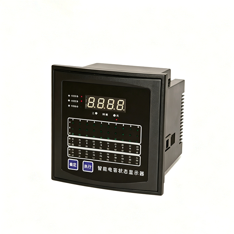
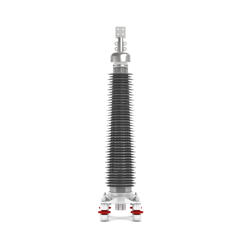
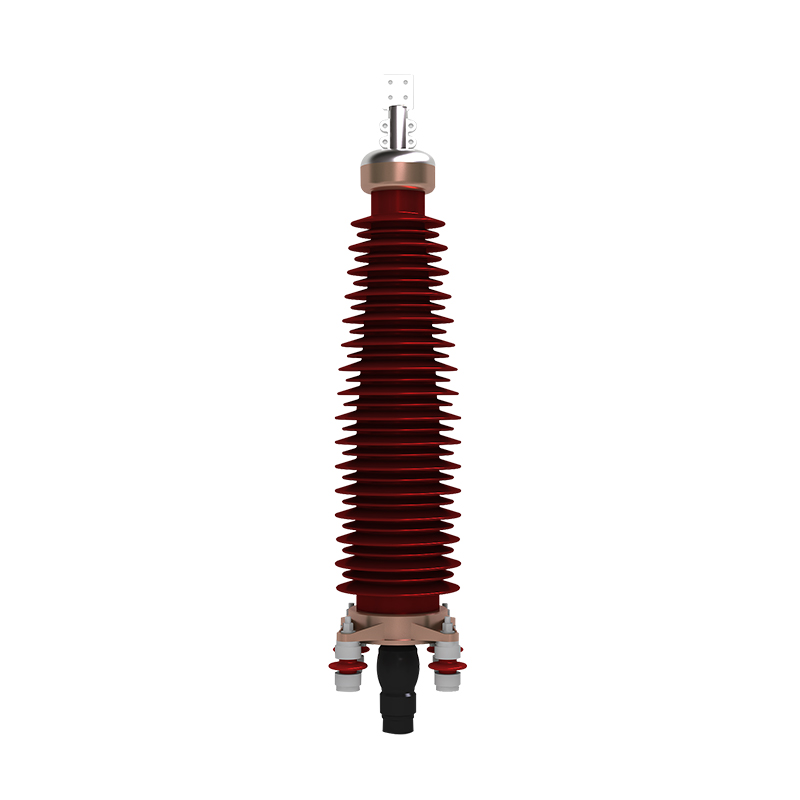
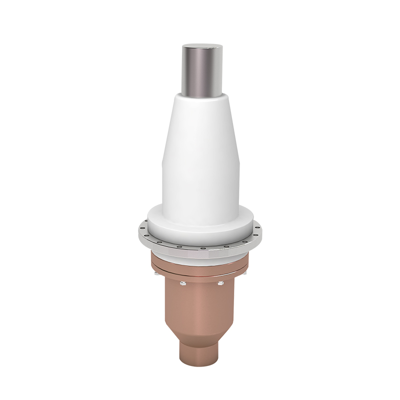
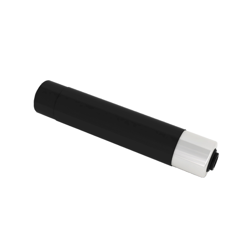
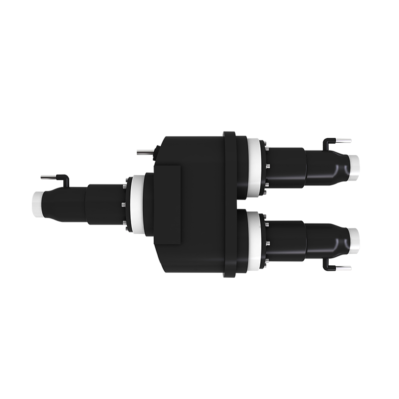
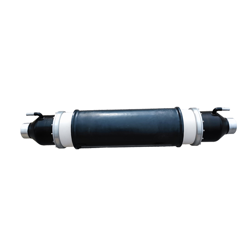
Recommended Products
The variety of models, to meet the development needs of various regions in the world.
Copyright © Shanghai Yongjin Electric Technology Co.,Ltd.

China Power Quality Solutions Supplier